1 basic principles of plc ladder diagram – Delta Electronics Programmable Logic Controller DVP-PLC User Manual
Page 16
1 Basic Principles of PLC Ladder Diagram
DVP-PLC Application Manual
1-12
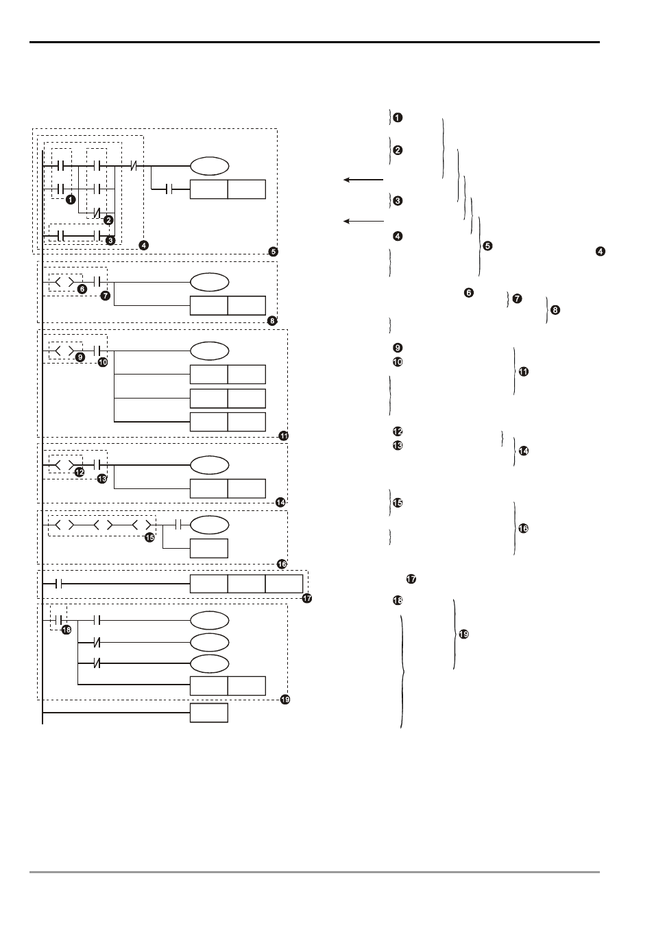
1.5 The Conversion of PLC Command and Each Diagram Structure
Ladder Diagram
X0
X2
X1
X1
M1
C0
Y0
SET
S0
M2
Y0
M0
X10
Y10
SET
S10
S0
S
X11
Y11
SET
S11
S10
S
SET
S12
SET
S13
X12
Y12
SET
S20
S11
S
X13
S0
RET
S20
S
S12
S
S13
S
X0
CNT
C0
K10
X1
M0
C0
X1
M2
RST
C0
M1
M2
END
LD X0
OR X1
LD X2
OR M0
ORI M1
ANB
LD M2
AND Y0
ORB
AN I X1
OUT Y0
AND C0
SET S0
STL S0
LD X10
OUT Y10
SET S10
STL S10
LD X11
OUT Y11
SET S11
SET S12
SET S13
STL S11
LD X12
OUT Y12
SET S20
STL S20
STL S12
STL S13
LD X13
OUT S0
RET
LD X0
CNT C0 K10
LD C0
MPS
AND X1
OUT M0
MRD
AN I X1
OUT M1
MPP
AN I M2
OUT M2
END
OR
block
ANI
Multiple
outputs
RST C0
OR
block
Series
connection blcok
AND
block
Parallel
connection block
The output will continue
following the status of
Step ladder Start
Status working item and
step point transfer
Withdraw S10 status
Withdraw X11 status
Status working item and
step point transfer
Withdraw S11 status
Withdraw X12 status
Status working item and
step point transfer
Bifurcation
convergence
End of step ladder
Status working item
and step point transfer
Return
Read C0
Multiple
outputs
End of program
Status S0 and X10 operation
Fuzzy Syntax
The correct ladder diagram analysis and combination should be conducted from up to down and left to right.
However, without adopting this principle, some instructions can make the same ladder diagram.