4 step ladder instructions – Delta Electronics Programmable Logic Controller DVP-PLC User Manual
Page 190
4 Step Ladder Instructions
DVP-PLC Application Manual
4-20
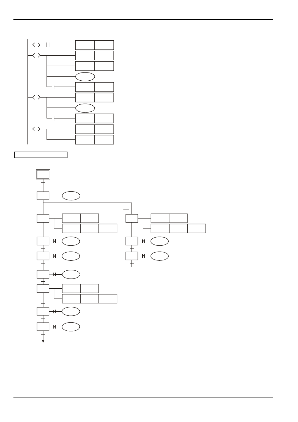
Ladder Diagram:
X15
SET
S10
S
S1
RST
Y4
S
S10
RST
Y1
Y0
X4
SET
S11
RST
Y2
S
S11
Y3
X1
SET
S12
SET
M1043
S
S12
RST
S12
Enter zero return mode
Clipping released
Descending stops
Robot arm ascends to upper limit (X4 On)
Right shifting stops
Robot arm left shifting to left limit (X1 On)
Enable zero return completed flag
Zero return operation completed
Auto Operation Modes
SFC:
S2
S20
S30
S31
M1044
X5
T0
Y1
SET
Y0
S32
X4
X2
S50
Y1
Y2
S2
X1
M1041
X0
Y4
TMR
T0
K30
S60
RST
X5
Y4
TMR
T2
K30
S70
T2
Y0
S80
X4
Y3
X1
S40
S41
X5
T1
SET
Y0
S42
X4
X3
Y2
X0
Y4
TMR
T1
K30
X3
X2
X4
X4
X5
X4
See also other documents in the category Delta Electronics Hardware:
- 1x9 Bi-Directional Transceiver Module OPBD-155F2J1R (7 pages)
- Single Mode SFP Transceiver LCP-1250B4MDRx (14 pages)
- LC-1250xxxx Series (10 pages)
- Human Machine Interface DOP-AS Series (329 pages)
- Analog Output Module DVP04DA-S (2 pages)
- DeviceNet Slave Communication Module IFD9502 (2 pages)
- LCP-155B4MSRx (12 pages)
- High-Speed PCI 12-Axis Motion Control Card PCI-DMC-B01 (528 pages)
- Network Device DVP01PU-S (2 pages)
- GBIC-1250D5MR (12 pages)
- SPBD-1250A4Q1RT (10 pages)
- SILM4015 (1 page)
- LCP-8500A4EDR (14 pages)
- 10GBASE-SR SFP+ Optical Transceiver LCP-10G3A4EDR (16 pages)
- LCP-155A4HSRx (11 pages)
- LCP-1250RJ3SR-L (9 pages)
- SILM320L (1 page)
- LCP-1250RJ3SR-S (9 pages)
- SIL530 (1 page)
- Extension Digital I/O Module DOP-EXIO28RAE (1 page)
- DVP Series PLC DVP04TC-H2 (2 pages)
- 1x9 Bi-Directional Transceiver Module OPBD-155F1J1R (7 pages)
- Distribution Box TAP-CN01/02/03 (2 pages)
- LCP-200A4HSR (9 pages)
- Pulse Generation Unit DVP01PU-H2 (2 pages)
- Power Connection Interface VFD-PSD01 (1 page)
- Programmable Logic Controller DVP04DA-H2 (2 pages)
- Single Mode SFP Transceiver LCP-1250B4QDRx (13 pages)
- LCP-155B4JSRx Series (12 pages)
- Series Temperature Controller DTD Series (2 pages)
- Brake Modules BUE Series (2 pages)
- PLC DVP Series DVP-SX (2 pages)
- Digital Keypad / Display ASD-PU-01A (1 page)
- Multimode SFP Transceiver LCP-1250A4FDRx (14 pages)
- HMU1362M (1 page)
- RPA-01 (1 page)
- THMR1395 (1 page)
- SFBD-155F2J1RM (7 pages)
- Program Transfer Module DVP-PCC01 (1 page)
- RTU-DNET (41 pages)
- AC Servo Drive ASDA-AB (37 pages)
- Digital Keypad / Display ASD-PU-01B (1 page)
- HMR1045 (1 page)
- CANopen Communication Module DVPCOPM-SL (2 pages)
- SPBD-1250B4Q1R (10 pages)