Delta Electronics Programmable Logic Controller DVP-PLC User Manual
Page 465
8 Application Instructions API 100-149
DVP-PLC Application Manual
8-63
API Mnemonic
Operands
Function
146
CVM
Valve Control
Controllers
ES/EX/SS SA/SX/SC EH/SV
Bit Devices
Word Devices
Program Steps
Type
OP
X Y M S K H
KnX KnY KnM KnS T
C
D
E
F
S
1
*
S
2
*
*
*
D
*
*
*
CVM: 7 steps
PULSE 16-bit 32-bit
ES EX SS SA SX SC EH SV ES EX SS SA SX SC EH SV ES EX SS SA SX SC EH SV
Operands:
S
1
: Target time of valve (absolute position) S
2
: Time from fully-closed to fully-open of valve (destination) D:
Output device
Explanations:
1. S
1
occupies 3 consecutive registers when in use. S
1
+ 0 are for the user to store the designated value; S
1
+ 1 (the
current position of the valve) and S
1
+ 2 are for storing the parameters recorded in the instruction and please DO
NOT use and alter these two registers.
2. D occupies 2 consecutive output devices when in use. D + 0 is the “open” contact and D + 1 is the “close” contact.
3. This instruction only supports EH2/SV and does not support EH.
4. The unit of time: 0.1 second. When the scan time of the program exceeds 0.1 second, DO NOT use this
instruction to adjust the position of the valve.
5. Frequency of the output device: 10Hz.
6. When the time of S
1
+ 0 > the fully-opened time set in S
2
, D + 0 will keep being On and D + 1 being Off. When
the time of S
1
+ 0 < 0, D + 0 will keep being Off and D + 1 being On.
7. When the instruction is enabled, the instruction will start to control the valve from “0” time position. Therefore, if
the user cannot be sure whether the valve is at “0” before executing the instruction, please designate S
1
+ 0 as
less than 0 and execute the instruction for S
2
(time) before sending in the correct target control time.
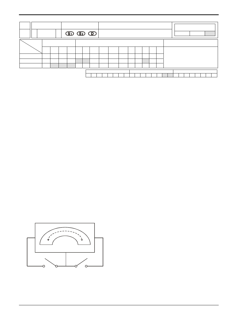
Program Example 1:
1. The control valve
Y0
Y1
Fully-closed
Fully-open
2. Definitions of the control valve:
a) When Y0 and Y1 = Off: No valve action