Delta Electronics Programmable Logic Controller DVP-PLC User Manual
Page 268
6 Application Instructions API 00-49
DVP-PLC Application Manual
6-56
API Mnemonic
Operands
Function
39
SFRD P
Shift Register Read
Controllers
ES/EX/SS SA/SX/SC EH/SV
Bit Devices
Word Devices
Program Steps
Type
OP
X Y M S K H
KnX
KnY
KnM KnS T C D E F
S
*
*
*
*
*
*
D
*
*
*
*
*
*
*
*
n
*
*
SFRD, SFRDP: 7 steps
PULSE 16-bit 32-bit
ES EX SS SA SX SC EH SV ES EX SS SA SX SC EH SV ES EX SS SA SX SC EH SV
Operands:
S
: Start No. of stack data D: Device of stack data read out n: Length of stack data
Explanations:
1. Range
of
n
: 2 ~ 512
2.
See the specifications of each model for their range of use.
3.
Flag: M1020 (zero flag)
4.
The stack data of n words starting from S are defined as “first-in, first-out” stack data and designate the first
device as the pointer. When the instruction is executed, the content in the pointer minuses 1, and the content in
the device designated by S will be written into the designated location in the “first-in, first-out” stack data
designated by the pointer. When the content in the pointer equals 0, this instruction will not process any new
value written in and the zero flag M1020 = On.
5.
This instruction adopts pulse execution instructions (SFRDP)
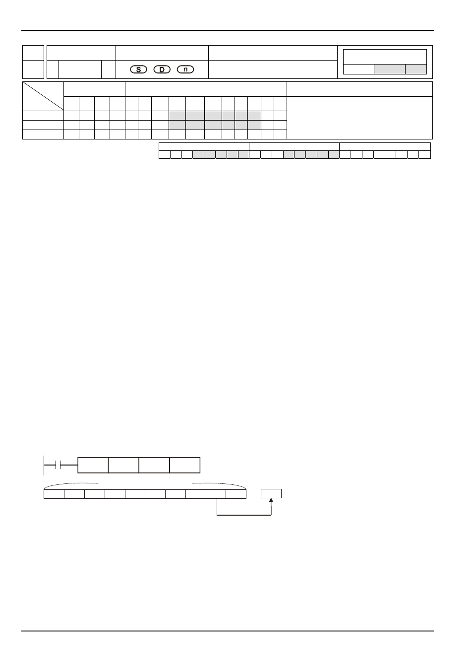
Program Example:
1.
When X0 = Off→On, the content in D1 will be sent to D21 and D9~D2 will shift to the right for 1 register (content
in D9 remains unchanged) and the content in D0 minus 1.
2.
The figure below illustrates the shift and reading in 1~3 execution of the instruction.
n
The content in D1 is sent to D21.
o
D9 ~ D2 shift to the right for 1 register.
p
The content in D0 minuses 1.
D9
D8
D7
D6
D5
D4
D3
D2
D1
D0
D21
X0
SFRDP
D0
K10
D21
n = 10 points
data read
pointer
Remarks:
This instruction can be used together with API 38 SFWR for the reading/writing of “first-in, first-out” stack data.