Delta Electronics Programmable Logic Controller DVP-PLC User Manual
Page 397
7 Application Instructions API 50-99
D V P - P L C A P P L I C AT I O N M A N U A L
7 - 113
Example 3:
Diagram of using PID instruction in temperature control (S
3
+ 4 = 1)
PID
Temperature instruction (SV)
Heating (MV)
Actual temperature
(PV)
Heater
Temperature
detection
device
Example 4:
How to adjust PID parameters
Assume that the transfer function of the controlled device G(S) in a control system is a first-order function
( )
a
s
b
s
G
+
=
(most models of motors are first-order function), SV = 1, and sampling time (T
S
) = 10ms, we
suggest you to follow the steps below for adjusting the parameters.
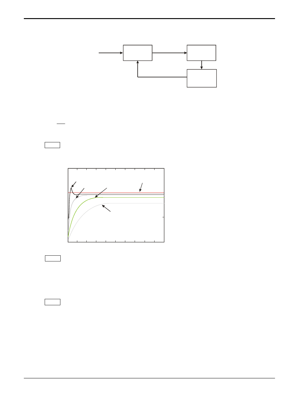
Step 1: Set K
I
and K
D
as 0 and K
P
as 5, 10, 20 and 40. Record the SV and PV respectively and the results
are as the figure below.
1.5
1
0.5
0
0
0.1
0.2
0.3
0.4
0.5
0.6
0.7
0.8
0.9
1
K =40
P
K =20
P
K =10
P
SV=1
K =5
P
Time (sec)
Step 2: From the figure, we can see that when K
P
= 40, there will be over-reaction, so we will not select it.
When K
P
= 20, the PV reaction curve will be close to SV and there will not be over-reaction, but due to its
fast start-up with big transient MV, we will consider to put it aside. When K
P
= 10, the PV reaction curve will
get close to SV value more smoothly, so we will use it. Finally when K
P
= 5, we will not consider it due to the
slow reaction.
Step 3: Select K
P
= 10 and adjust K
I
from small to big (e.g. 1, 2, 4 to 8). K
I
should not be bigger than K
P
.
Adjust K
D
from small to big (e.g. 0.01, 0.05, 0.1 and 0.2). K
D
should not exceed 10% of K
P
. Finally we
obtain the figure of PV and SV below.