Delta Electronics Programmable Logic Controller DVP-PLC User Manual
Page 497
9 Application Instructions API 150-199
DVP-PLC Application Manual
9-25
Y6).
- When in backward direction, the content in the present value register will decrease.
10. For SC series MPU, S
1
is the 32-bit data stored in the present value registers D1348 (low word) and D1349
(high word) of CH0 (Y10) or the 32-bit data stored in the present value registers D1350 (low word) and D1351
(high word) of CH1 (Y11). When in backward direction, the content in the present value register will decrease.
When the program goes from STOP to RUN or from RUN to STOP, the content in the present value register
will remain unchanged.
11. When DRVI instruction is executing pulse output, you cannot change the content of all operands. The changes
will be valid next time when DRVI instruction is enabled.
12. For EH/EH2/SV series MPU, when the drive contact of DRVI instruction is Off, even the indication flag M1336
sent by CH0 pulses, M1337 sent by CH1 pulses, M1522 sent by CH2 pulses and M1523 sent by CH3 pulses
are “On”, DRVI instruction will not be driven again.
13. When the absolute value of the input frequency of DDRVI insturction in EH/EH2/SV series MPU is larger than
200KHz, the output will be operated at 200KHz. When the absolute value of the input frequency is smaller
than 10Hz, the output will be operated at 10Hz.
14. D1343 (D1353) is for setting up the time of the first acceleartion segment and last deceleration segment of
CH0 (CH1). The acceleration and deceleration time of EH/EH2/SV series MPU shall not be shorter than 10ms.
The output will be operated for 10ms if the time is shorter than 10ms or longer than 10,000ms (default setting
= 100ms). The time range for SC series MPU is 50 ~ 20,000ms. The output will be operated for 20,000ms or
50ms if the time set is longer than 20,000ms or shorter than 50ms.
15. D1340 (D1352) is for setting up the start/end frequency of Y10 (Y11). If S
2
is less than or equals start/end
frequency, the pulse output frequency will be executed by the start/end frequency.
16. For EH/EH2/SV series MPU, M1305 (M1306) is the direction signal of CH0 (CH1). When S
1
is a positive
number, the output will be operated in a forward direction and M1305 (M1306) will be Off. When S
1
is a
negative number, the output will be operated in a backward direction and M1305 (M1306) will be On.
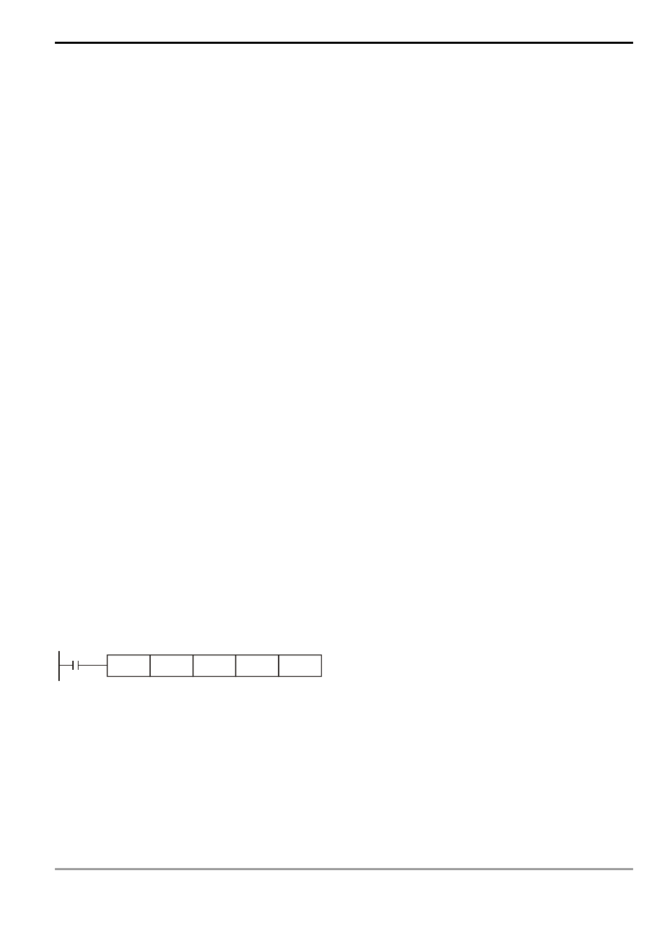
Program Example:
When M10= On, Y0 will output 20,000 pulses (relative designation) at 2KHz. Y5 = On indicates the pulses are
executed in forward direction.
M10
DRVI
K20000
K2000
Y0
Y5
Remarks:
1.
Explanations on EH/EH2/SV series MPU:
a) Relative position control: Designating the traveling distance starting from the current position by “+/ -“ signs;
also known as a relative driving method.