3 basic instructions – Delta Electronics Programmable Logic Controller DVP-PLC User Manual
Page 161
3 Basic Instructions
DVP-PLC Application Manual
3-7
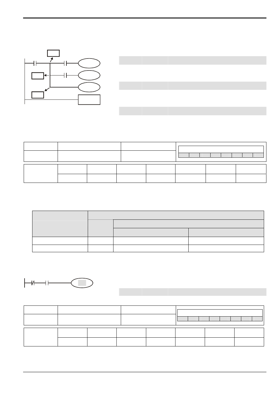
Program Example:
Ladder diagram:
Instruction code:
Operation:
LD
X0
Loading in contact A of X0
MPS
Saving into stack
AND
X1
Connecting to contact A of X1 in series
OUT Y1
Driving
Y1
coil
MRD
Reading from stack
AND
X2
Connecting to contact A of X2 in series
OUT
M0
Driving M0 coil
MPP
Reading from stack and pop pointer
OUT Y2
Driving
Y2
coil
X0
Y1
X1
M0
X2
Y2
END
MPP
MRD
MPS
END
Program
ends
Mnemonic Function
Program
steps
OUT
Output coil
1
Controllers
ES
EX
SS
SA
SX
SC
EH
SV
X0 ~ X377
Y0 ~ Y377 M0 ~ M4095 S0 ~ S1023
T0 ~ T255
C0 ~ C255
D0 ~ D9999
Operand
-
9
9
9
-
-
-
Explanations:
1. To output the logical operation result before OUT instruction into a designated device.
2. Actions of coil contact:
OUT instruction
Contact
Operational result
Coil
A contact (normally open)
B contact (normally closed)
FALSE Off
Off
On
TRUE On
On
Off
Program Example:
Ladder diagram:
Instruction code:
Operation:
LDI
X0
Loading in contact B of X0
AND
X1
Connecting to contact A of X1 in series
X0
X1
Y1
OUT
Y1
Driving Y1 coil
Mnemonic
Function
Program Steps
SET
Latched (On)
1
Controllers
ES
EX
SS
SA
SX
SC
EH
SV
X0 ~ X377
Y0 ~ Y377 M0 ~ M4095 S0 ~ S1023
T0 ~ T255
C0 ~ C255
D0 ~ D9999
Operand
-
9
9
9
-
-
-
Explanations: