Delta Electronics Programmable Logic Controller DVP-PLC User Manual
Page 305
7 Application Instructions API 50-99
D V P - P L C A P P L I C AT I O N M A N U A L
7-21
- D: Designated mode (can only be M1152)
4.
This mode can only be used once. For EH/EH2/SV series MPU, this mode can only be used in the hardware
high speed counter C241 ~ C254. Please enter the set values in every register in the table before executing the
instruction.
5.
When this mode is enabled, PLC will first acquire the set values in D0 and D1 as the target value for the first
comparison section. At the same time, the index value displayed in D1152 will be 0, indicating that PLC
performs the comparison based on the group 0 data.
6.
When the group 0 data in the table have been compared, PLC will first execute at the frequency set in group 0
data (D2, D3) and copy the data to D1152 and D1153, determining if the comparison reaches the target number
of groups. If the comparison reaches the target, M1153 will be On; if the comparison has not reached the final
group, the content in D1151 will plus 1 and continue the comprison for the next group.
7.
M1153 is the flag for the completion of one execution of the table, can be Off by the user. Or when the next
comparion cycle takes place and the group 0 data has been compared, PLC will automatically reset the flag.
8.
If you wish to use this mode with PLSY instruction, please preset the value in D1152.
9.
If you wish to stop the execution at the last row, please set the value in the last row K0.
10. When the drive contact of the instruction X10 goes Off, the execution of the instruction will be interrupted and
the content in D1151 (table counting register) will be reset to 0.
11. When in this mode, the frequency of the input counting pulses cannot exceed 50KHz or the neighboring two
groups of comparative values cannot differ by 1; otherwise there will not be enough time for the PLC to react
and result in errors.
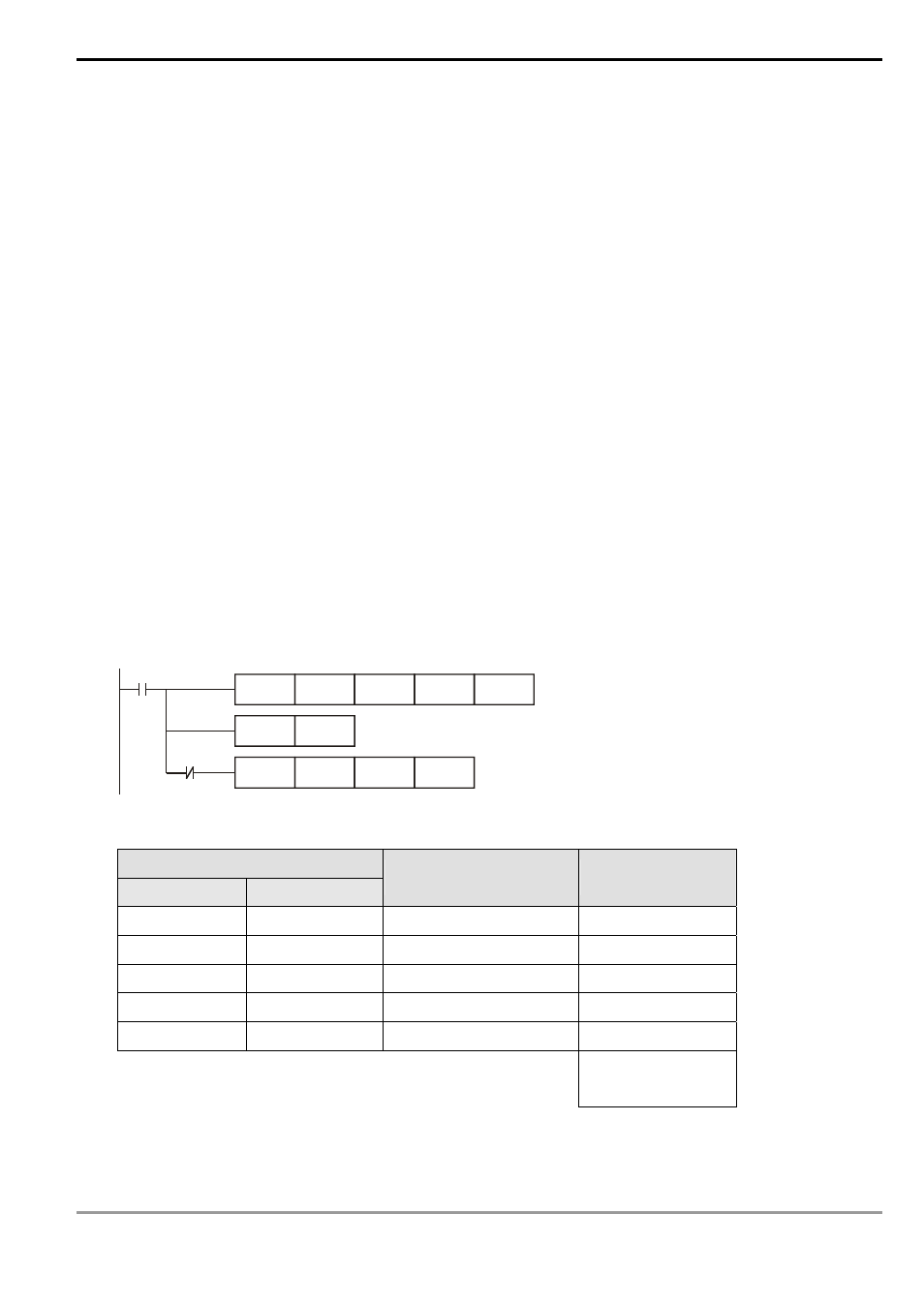
X10
DHSZ
D0
K5
C251
M1152
PLS
M0
DPLSY
D1152
K0
Y0
M0
The comparison table:
32-bit data for comparison
High word
Low word
Pulse output frequency
0 ~ 200KHz
Table counting
register D1151
D1 (K0)
D0 (K0)
D3,
D2
(K5,000)
0
D5 (K0)
D4 (K100)
D7,
D6
(K10,000)
1
D9 (K0)
D8 (K200)
D11,
D10 (K15,000)
2
D13 (K0)
D12 (K300)
D15,
D14
(K6,000)
3
D17 (K0)
D16 (K400)
D19,
D18
(K0)
4
0→1→2→3→4
Cyclic scan