Delta Electronics Programmable Logic Controller DVP-PLC User Manual
Page 444
8 Application Instructions API 100-149
DVP-PLC Application Manual
8-42
API Mnemonic
Operands
Function
129
D INT P
Float to Integer
Controllers
ES/EX/SS SA/SX/SC EH/SV
Bit Devices
Word Devices
Program Steps
Type
OP
X Y M S K H
KnX
KnY KnM KnS T
C
D
E
F
S
*
D
*
INT, INTP: 5 steps
DINT, DINTP: 9 steps
PULSE 16-bit 32-bit
ES EX SS SA SX SC EH SV ES EX SS SA SX SC EH SV ES EX SS SA SX SC EH SV
Operands:
S
: Source device D: Converted result
Explanations:
1. S occupies 2 consecutive devices. See the specifications of each model for their range of use.
2. Flags: M1020 (zero flag); M1021 (borrow flag); M1022 (carry flag)
3. The binary floating point value of the register designated by S is converted to BIN integer and stored in the
register designated by D. The decimal of BIN integer is left out.
4. This instruction is the inverse operation of API 49 FLT instruction.
5. If the converstion result = 0, the zero flag M1020 = On
If there is any decimal left out, the borrow flag M1021 = On.
If the result exceeds the range listed below, the carry flag M1022 = On.
16-bit instruction: -32,768 ~ 32,767
32-bit instruction: -2,147,483,648 ~ 2,147,483,647
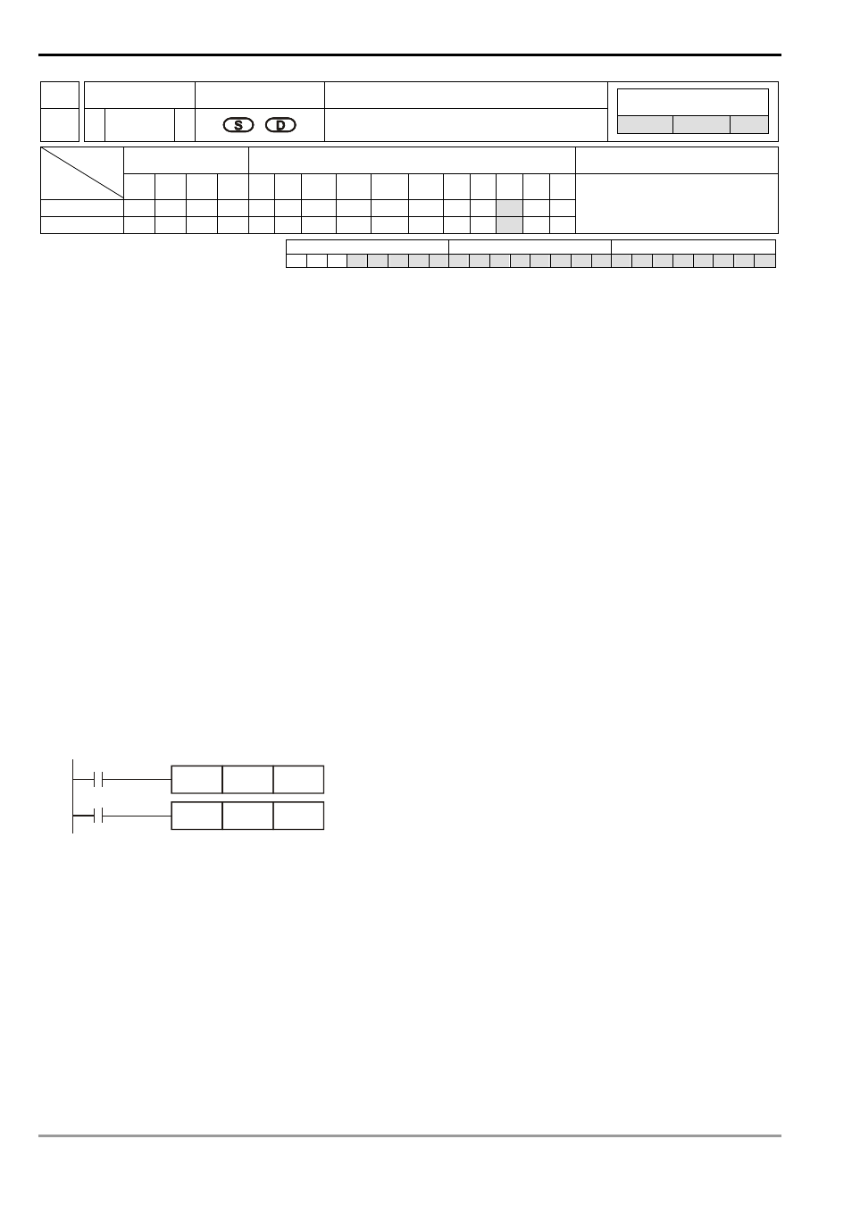
Program Example:
1. When X0 = On, the binary floating point (D1, D0) will be converted into BIN integer and the result will be stored
in (D10). The decimal of BIN integer will be left out.
2. When X1 = On, the binary floating point (D21, D20) will be converted into BIN integer and the result will be
stored in (D31, D30). The decimal of BIN integer will be left out.
INT
X0
D0
D10
DINT
X1
D20
D30
Remarks:
For floating point operations, see “5.3 Handling of Numeric Values”.