Delta Electronics Programmable Logic Controller DVP-PLC User Manual
Page 373
7 Application Instructions API 50-99
D V P - P L C A P P L I C AT I O N M A N U A L
7-89
When STX, ETX1 and EXT2 are in use, please be aware of the On and Off of the special auxiliary relays M1126
and M1130.
6. M1143 is for the selection of ASCII mode or RTU mode. On = RTU mode; Off = ASCII mode.
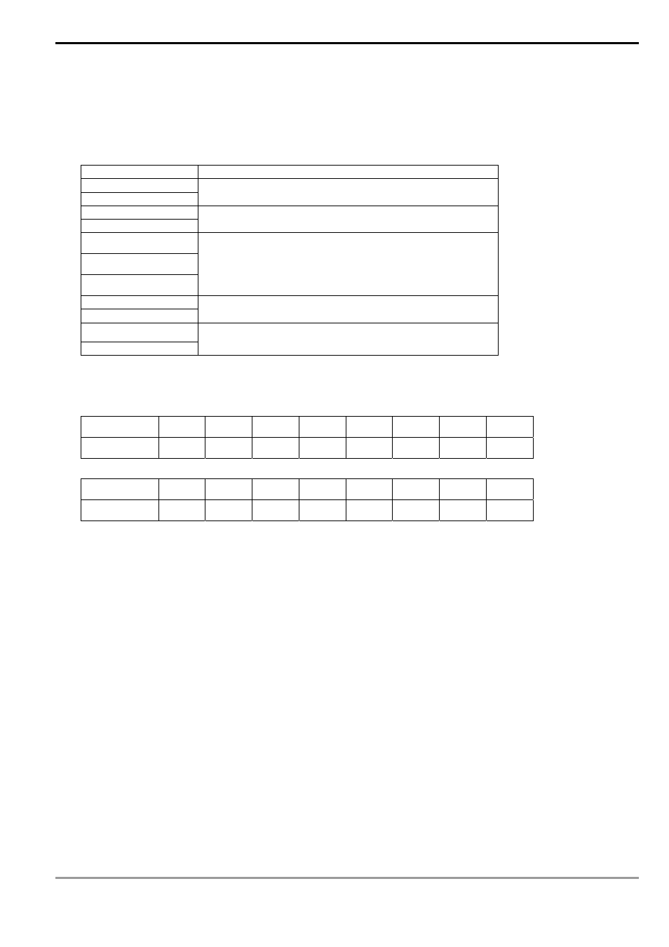
Take the standard Modbus format for example:
In ASCII mode (M1143 = Off)
STX
Start word = ‘:’ (3AH)
Address Hi
Address Lo
Communication address:
The 8-bit address consists of 2 ASCII codes
Function Hi
Function Lo
Function code:
The 8-bit function code consists of 2 ASCII codes
DATA (n-1)
…….
DATA 0
Data:
The n × 8-bit data consists of 2n ASCll codes
LRC CHK Hi
LRC CHK Lo
LRC checksum:
The 8-bit checksum consists of 2 ASCll code
END Hi
END Lo
End word:
END Hi = CR (0DH), END Lo = LF(0AH)
The communication protocol is in Modbus ASCII mode, i.e. every byte is composed of 2 ASCII characters. For
example, 64Hex is ‘64’ in ASCII, composed by ‘6’ (36Hex) and ‘4’ (34Hex). Every hex ‘0’…’9’, ‘A’…’F’
corresponds to an ASCII code.
Character ‘0’ ‘1’ ‘2’ ‘3’ ‘4’ ‘5’ ‘6’ ‘7’
ASCII
code 30H 31H 32H 33H 34H 35H 36H 37H
Character ‘8’ ‘9’ ‘A’ ‘B’ ‘C’ ‘D’ ‘E’ ‘F’
ASCII
code 38H 39H 41H 42H 43H 44H 45H 46H
Start word (STX):
Fixed as ‘:’ (3AH)
Address:
‘0’ ‘0’: Broadcasting to all drivers
‘0’ ‘1’: To the driver at address 01
‘0’ ‘F’: To the driver at address 15
‘1’ ‘0’: To the driver at address 16
….and so on, maximum to the driver at address 255 (‘F’ ‘F’)
Function code:
‘0’ ‘3’: Read contents of many registers
‘0’ ‘6’: Write 1 word to register
‘1’ ‘0’: Write in contents of many registers
Data characters: The data sent by the user.
LRC checksum:
LCR checksum is 2’s complement of the value added from Address to Data Content.
For example: 01H + 03H + 21H + 02H + 00H + 02H = 29H. 2’s complement of 29H = D7H
End word (END):