Delta Electronics Programmable Logic Controller DVP-PLC User Manual
Page 389
7 Application Instructions API 50-99
D V P - P L C A P P L I C AT I O N M A N U A L
7-105
API Mnemonic Operands
Function
86
VRSC P
Volume Scale
Controllers
ES/EX/SS SA/SX/SC EH/SV
Bit Devices
Word Devices
Program Steps
Type
OP
X Y M S K H
KnX KnY KnM KnS T
C
D
E
F
S
*
*
D
*
*
*
*
*
*
*
*
VRSC, VRSCP: 5 steps
PULSE 16-bit 32-bit
ES EX SS SA SX SC EH SV ES EX SS SA SX SC EH SV ES EX SS SA SX SC EH SV
Operands:
S
: No. of VR D: Device for storing the scale of VR
Explanations:
1. Range
of
S
: 0 ~ 7; without function card: 0 ~ 1
2. See the specifications of each model for their range of use.
3. VRSC instruction is used for reading 2 points (No.0, No.1) of PLC or the VR rotary switch scale (0 ~ 10) in the 6
points of the function cards (No.2 ~ No.7) and storing the data in D. If the position of the VR falls in the middle of
two scales, VRSC will round up the value into an integer of 0 ~ 10.
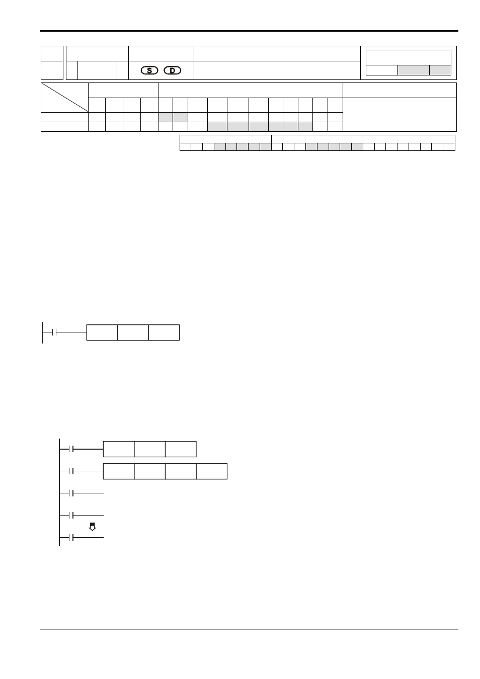
Program Example 1:
When X0 = On, the scale of VR0 (0 ~ 10) will be stored in D10.
X0
VRSC
K0
D10
Program Example 2:
1. When the VR is used as DIP switch, they will correspond to scale 0 ~ 10 and only one of M10 ~ M20 will be On.
Use API 41 DECO instruction to decode the scales into M10 ~ M25.
2. When X0 = On, store the scale (0 ~ 10) of VR1 into D1.
3. When X1 = On, use API 41 DECO to decode the scales into M10 ~ M25.
X0
VRSC
K1
D1
X1
DECO
D1
M10
K4
M10
M11
M20
On when the scale is 0
On when the scale is 1
On when the scale is 10
Remarks:
If the MPU is not inserted with a VR extension card, and the No. of the rotary switches inVRRD or VRSC instruction in
the program are set as K2 ~ K7, errors will occur in the execution of grammar check.