Delta Electronics Programmable Logic Controller DVP-PLC User Manual
Page 548
9 Application Instructions API 150-199
DVP-PLC Application Manual
9-76
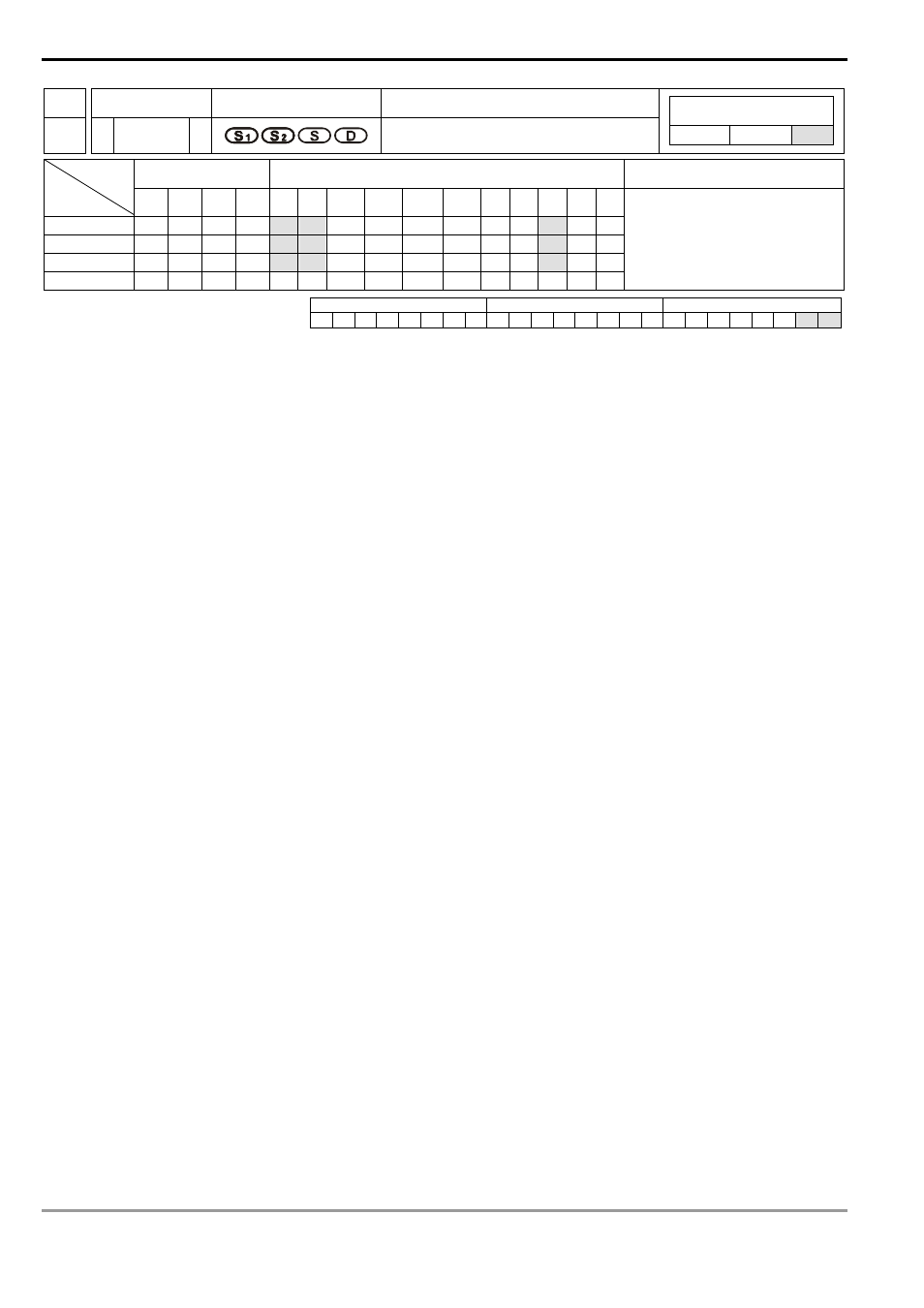
API Mnemonic
Operands
Function
191
D PPMR
2-Axis Relative Point to Point Motion
Controllers
ES/EX/SS SA/SX/SC EH/SV
Bit Devices
Word Devices
Program Steps
Type
OP
X Y M S K H
KnX
KnY KnM KnS T
C
D
E
F
S
1
*
*
*
S
2
*
*
*
S
*
*
*
D
*
DPPMR: 17 steps
PULSE 16-bit 32-bit
ES EX SS SA SX SC EH SV ES EX SS SA SX SC EH SV ES EX SS SA SX SC EH SV
Operands:
S
1
: Number of output pulses of X axis S
2
: Number of output pulses of Y axis S: Max. point to point output
frequency D: Pulse output device
Explanations:
1.
Flags: M1029, M1030, M1334, M1335. See remarks for more details.
2.
This instruction only supports EH2/SV series MPU, not EH series. In terms of pulse output methods, this
instructin only supports “pulse + direction” mode.
3.
S
1
and S
2
are the designated (relative designation) number of output pulses in X axis (Y0 or Y4) and Y axis (Y2
or Y6). The range of the number is -2,147,483,648 ~ +2,147,483,647 (+/- represents the forward/backward
direction). When in forward direction, the pulse present value registers CH0 (D1337 high word, D1336 low word),
CH1 (D1339 high word, D1338 low word), CH2 (D1376 high word, D1375 low word) and CH3 (D1378 high word,
D1377 low word) will increase. When in backward direction, the present value will decrease.
4.
D can designate Y0 and Y4.
When Y0 is designated:
Y0 refers to 1
st
group X-axis pulse output device.
Y1 refers to 1
st
group X-axis direction signal.
Y2 refers to 1
st
group Y-axis pulse output device.
Y3 refers to 1
st
group Y-axis direction signal.
Y4 refers to 2
nd
group X-axis pulse output device.
Y5 refers to 2
nd
group X-axis direction signal.
Y6 refers to 2
nd
group Y-axis pulse output device.
Y7 refers to 2
nd
group Y-axis direction signal.
When direction signal outputs, Off will not occur immediately after the pulse output is over. Direction signal will
turn Off when the drive contact is Off.
5.
D1340 (D1379) refers to the settings of the start/end frequencies of the 1
st
/2
nd
2-axis motion. D1343 (D1381)
refers to the time of the first acceleration segment and last deceleration segment of the 1
st
/2
nd
2-axis motion.
The time shall be longer than 10ms. If the time is shorter than 10ms or longer than 10,000ms, the output will be
operated at 10ms. Default setting = 100ms.
6.
If the maximum output frequency setting is less than 10Hz, the output will be operated at 10Hz. If the setting is
more than 200KHz, the output will be operated at 200KHz.