4 step ladder instructions – Delta Electronics Programmable Logic Controller DVP-PLC User Manual
Page 177
4 Step Ladder Instructions
DVP-PLC Application Manual
4-7
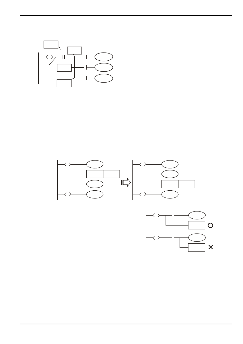
The position of MPS/MRD/MPP instruction:
Ladder diagram:
Y1
S
S
M0
Y2
X2
n
X3
X1
X0
MPP
MRD
MPS
BUS
LD X0
Instruction code:
STL Sn
LD X0
MPS
AND X1
OUT Y1
MRD
AND X2
OUT M0
MPP
AND X3
OUT Y2
Explanation:
MPS/MRD/MPP instruction cannot
be used directly on the new bus.
You have to execute LD or LDI
instruction first before applying
MPS/MRD/MPP.
8. Other Points to Note:
The instruction used for transferring the step (SET S□ or OUT S□) can only be executed after all the relevant
outputs and actions in the current status are completed. See the figure below. The executed results by the PLC are
the same, but if there are many conditions or actions in S10, it is recommended that you modify the diagram in the
left hand side into the diagram in the right hand side. SET S20 is only executed after all relevant outputs and
actions are completed, which is a more explicit sequence.
SET
Y0
S10
S
S20
S
Y2
S20
Y1
SET
Y0
S10
S
S20
S
Y2
S20
Y1
Make sure to add RET instruction after STL at the end of
the step ladder diagram.
S0
S20
S
RET
X1
S0
S20
S
RET
X1
4.4 Things to Note for Designing a Step Ladder Program
1. The first step in the SFC is called the “initial step", S0 ~ S9. Use the initial step as the start of a sequence and end a
complete sequence with RET instruction.
2. If STL instruction is not in use, step S can be a general-purpose auxiliary relay.
3. When STL instruction is in use, the No. of step S cannot be repeated.
4. Types of sequences: