Delta Electronics Programmable Logic Controller DVP-PLC User Manual
Page 334
7 Application Instructions API 50-99
D V P - P L C A P P L I C AT I O N M A N U A L
7-50
API Mnemonic
Operands
Function
64
TTMR
Teaching Timer
Controllers
ES/EX/SS SA/SX/SC EH/SV
Bit Devices
Word Devices
Program Steps
Type
OP
X Y M S K H
KnX
KnY KnM KnS T
C
D
E
F
D
*
n
*
*
TTMR: 5 steps
PULSE 16-bit 32-bit
ES EX SS SA SX SC EH SV ES EX SS SA SX SC EH SV ES EX SS SA SX SC EH SV
Operands:
D
: Device No. for storing the “On” time of button switch n: Multiple setting
Explanations:
1. D will occupy 2 consecutive devices.
2. Range
of
n
: 0 ~ 2
3. See the specifications of each model for their range of use.
4. For SA series MPU, TTMR instruction can be used 8 times in the program.
5. The “On” time (unit: 100ms) of the external button switch is stored in device No. D + 1. The “On” time (unit:
second) of the switch is multiplied by n and stored in D.
6. Multiple
setting:
When n = 0, unit of D = second
When n = 1, unit of D = 100ms (D × 10)
When n = 2, unit of D = 10ms (D × 100)
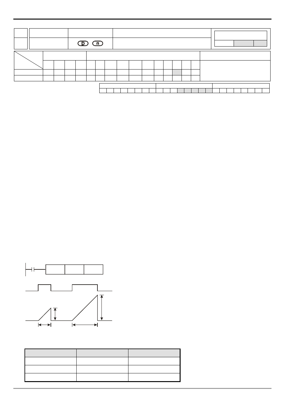
Program Example 1:
1. The “On” (being pressed) time of button switch X0 is stored in D1. The setting of n is stored in D0. Therefore, the
button switch will be able to adjust the set value in the timer.
2. When X0 goes Off, the content in D1 will be cleared to 0, but the content in D0 will remain.
X0
TTMR
D0
K0
X0
D1
D0
D0
D1
T
T
On time (sec)
On time (sec)
3. Assume the “On” time of X0 is T (sec.), see the relation between D0, D1 and n in the table below.
n
D0
D1 (unit: 100ms)
K0 (unit: s)
1 × T
D1 = D0 × 10
K1 (unit: 100 ms)
10 × T
D1 = D0
K2 (unit: 10 ms)
100 × T
D1 = D0/10