2 functions of devices in dvp-plc – Delta Electronics Programmable Logic Controller DVP-PLC User Manual
Page 32
2 Functions of Devices in DVP-PLC
DVP-PLC Application Manual
2-4
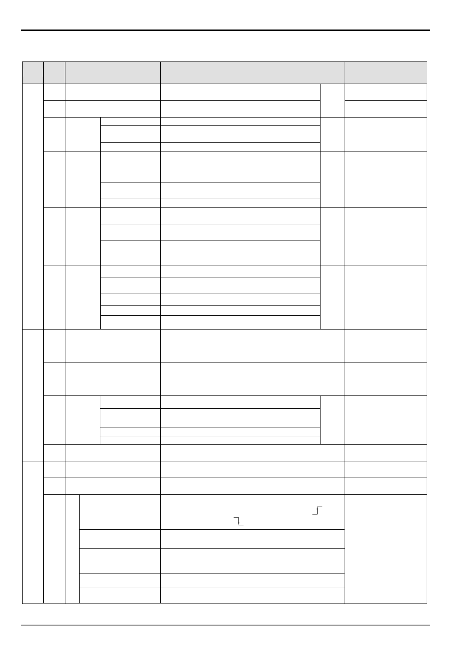
EH/EH2/SV series MPU:
Type
Device
Item
Range
Function
X
External input relay
X0 ~ X377, 256 points, octal
Corresponds to external
input points
Y
External output relay
Y0 ~ Y377, 256 points, octal
Total
512
points Corresponds to external
output points
General purpose M0 ~ M499, 500 points (*2)
Latched
M500 ~ M999, 500 points (*3)
M2000 ~ M4095, 2,096 points (*3)
M
Auxiliary
relay
Special purpose M1000 ~ M1999, 1,000 points (some are latched)
Total
4,096
points
The contact can be
On/Off in the program.
100ms
T0 ~ T199, 200 points (*2)
T192 ~ T199 is for subroutine
T250~T255, 6 accumulative points (*4)
10ms
T200 ~ T239, 40 points (*2)
T240 ~ T245, 6 accumulative points (*4)
T Timer
1ms
T246 ~ T249, 4 accumulative points (*4)
Total
256
points
Timer indicated by TMR
instruction. If timing
reaches its target, the T
contact of the same No.
will be On.
16-bit counting
up
C0 ~ C99, 100 points (*2)
C100 ~ C199, 100 points (*3)
32-bit counting
up/down
C200 ~ C219, 20 points (*2)
C220 ~ C234, 15 points (*3)
C Counter
32-bit high-speed
counter
C235 ~ C244, 1-phase 1 input, 10 points (*3)
C246 ~ C249, 1-phase 2 inputs, 4 points(*3)
C251 ~ C254, 2-phases 2 inputs, 4 points (*3)
Total
253
points
Counter indicated by
CNT (DCNT)
instruction. If counting
reaches its target, the C
contact of the same No.
will be On.
Initial step point
S0 ~ S9, 10 points (*2)
Zero return
S10 ~ S19, 10 points (used with IST instruction)
(*2)
General purpose S20 ~ S499, 480 points (*2)
Latched
S500 ~ S899, 400 points (*3)
Relay (
bit)
S Step
Alarm
S900 ~ S1023, 124 points (*3)
Total
1,024
points
Used for SFC.
T
Present value of timer
T0 ~ T255, 256 points
When the timing
reaches the target, the
contact of the timer will
be On.
C
Present value of counter
C0 ~ C199, 16-bit counter, 200 points
C200 ~ C254, 32-bit counter, 53 points
When the counting
reaches the target, the
contact of the counter
will be On.
General purpose D0 ~ D199, 200 points, (*2)
Latched
D200 ~ D999, 800 points (*3)
D2000 ~ D9999, 8,000 points (*3)
Special purpose D1000 ~ D1999, 1,000 points
D
Data
register
Index indication
E0 ~ E7, F0 ~ F7, 16 points (*1)
Total
10,000
points
Memory area for data
storage; E, F can be
used for index
indication.
Regist
er (word
dat
a)
N/A File register
K0 ~ K9,999 (10,000 points) (*4)
Expanded register for
data storage.
N
For master control loop
N0 ~ N7, 8 points
Control point for main
control loop
P
For CJ, CALL instructions
P0~P255, 256 points
Position index for CJ
and CALL
External interruption
I00□(X0), I10□(X1), I20□(X2), I30□(X3), I40□(X4),
I50□(X5), 6 points (□ = 1, rising-edge trigger
, □ =
0, falling-edge trigger
)
Timed interruption
I6□□, I7□□, 2 points(□□ = 1~99ms) time base = 1ms
I8□□, 1 point (□□ = 1~99, time base = 0.1ms)
Interruption inserted
when high-speed
counter reaches target
I010, I020, I030, I040, I050, I060, 6 points
Pulse interruption
I110, I120, I130, I140, 4 points
Pointer
I
Interruptio
n
Communication
interrruption
I150, I160, I170, 3 points
Position index for
interruption subroutine.