3 how to edit ladder diagram, 1 basic principles of plc ladder diagram – Delta Electronics Programmable Logic Controller DVP-PLC User Manual
Page 7
1 Basic Principles of PLC Ladder Diagram
DVP-PLC Application Manual
1-3
the bigger the error is to the control. The control may even be out of control. In this case, you have to choose a PLC
with faster scan speed. Therefore, the scan speed is an important specification requirement in a PLC. Owing to the
advancement in microcomputer and ASIC (IC for special purpose), there has been great improvement in the scan
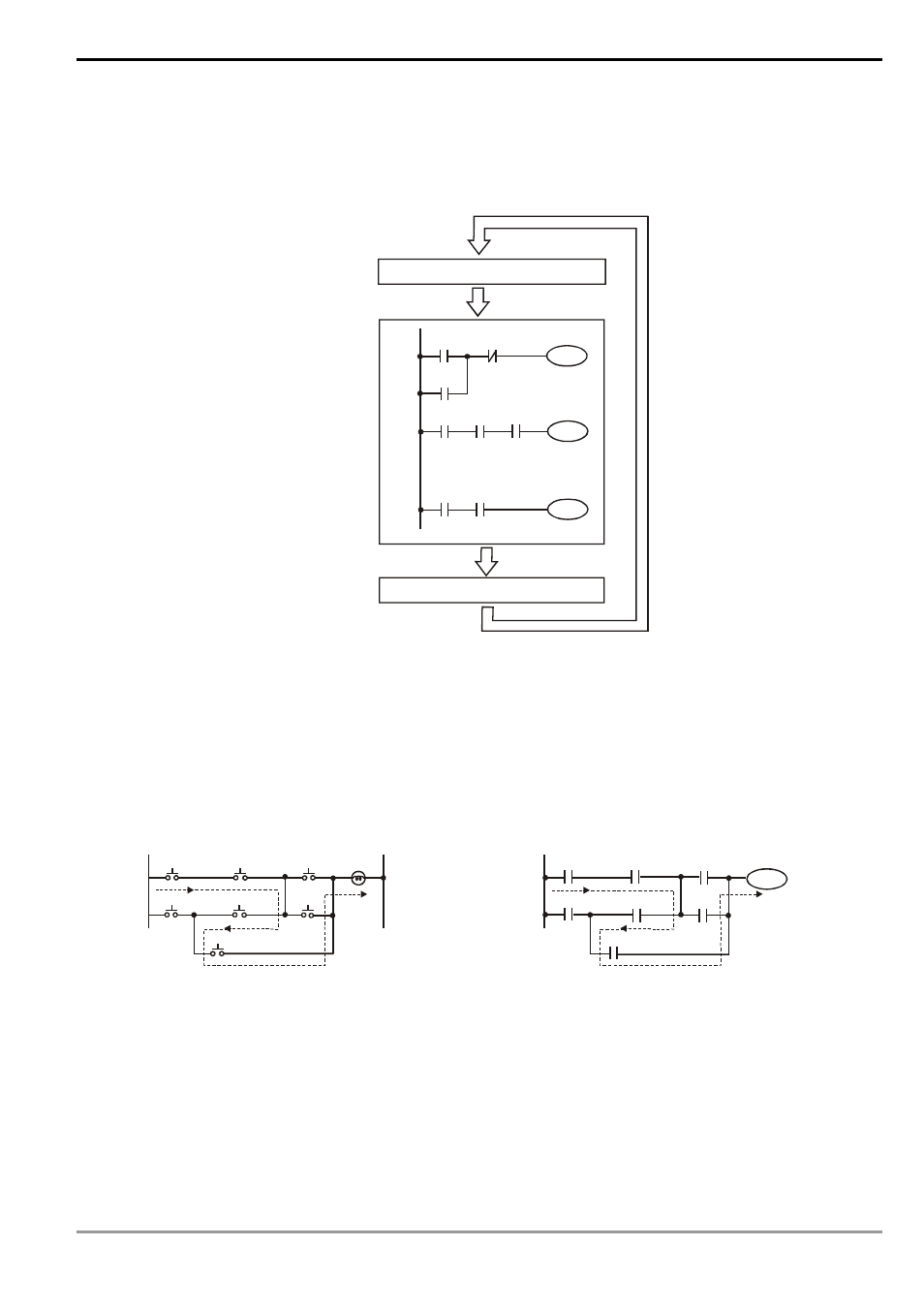
speed of PLC nowadays. See the figure below for the scan of the PLC ladder diagram program.
The output result is calculated
based on the ladder diagram.
(The result has not yet sent to the
external output point, but the
internal device will perform an
immediate output.)
Y0
X0
X1
Y0
Start
M100 X3
Y1
X10
:
:
X100 M505
Y126
End
Send the result to the output point
Read input status from outside
Executing in cycles
Besides the difference in the scan time, PLC ladder and traditional ladder diagram also differ in “reverse current”.
For example, in the traditional ladder diagram illustrated below, when X0, X1, X4 and X6 are On and others are Off,
Y0 output on the circuit will be On as the dotted line goes. However, the PLC ladder diagram program is scanned from
up to down and left to right. Under the same input circumstances, the PLC ladder diagram editing tool WPLSoft will be
able to detect the errors occurring in the ladder diagram.
Reverse current of traditional ladder diagram
X6
X0
X1
X2
X3
X4
X5
a
b
Y0
Reverse current of PLC ladder diagram
X6
X0
Y0
X1
X2
Y0
X3
X4
X5
a
b
Error detected in the third row
1.3 How to Edit Ladder Diagram
Ladder diagram is a diagram language frequently applied in automation. The ladder diagram is composed of the
symbols of electric control circuit. The completion of the ladder diagram by the ladder diagram editor is the completion
of the PLC program design. The control flow illustrated by diagram makes the flow more straightforward and
acceptable for the technicians of who are familiar with the electric control circuit. Many basic symbols and actions in