Delta Electronics Programmable Logic Controller DVP-PLC User Manual
Page 409
8 Application Instructions API 100-149
DVP-PLC Application Manual
8-7
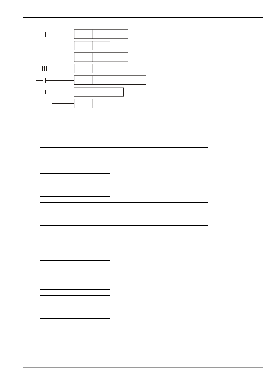
MOV
D1120
H87
M1002
SET
M1120
MOV
D1129
K100
M1127
RST
M1127
receiving
completed
Set up communication protocol 9600, 8, E, 1
Retain communication protocol
Set up communication time-out: 100ms
Process of receiving data
SET
M1122
Set up sending request
X1
X0
MODWR
K1
H0100
H1770
Set up communication instruction device address 01
data address H0100 data H1770
The received data are stored in D1070 ~ D1085 in ASCII format.
PLC will automatically convert the data into numerals and store
them in D1050 ~ D1055.
Sending/receiving of data is completed. The flag is reset.
PLC VFD-B, PLC sends: “ 01 06 0100 1770 71 ”
VFD-B PLC, PLC receives: “ 01 06 0100 1770 71 ”
Registers for sent data (sending messages)
Register DATA
Explanation
D1089 low
‘0’
30 H
ADR 1
D1089 high
‘1’
31 H
ADR 0
Address of AC motor drive:
ADR (1,0)
D1090 low
‘0’
30 H
CMD 1
D1090 high
‘6’
36 H
CMD 0
Instruction code: CMD (1,0)
D1091 low
‘0’
30 H
D1091 high
‘1’
31 H
D1092 low
‘0’
30 H
D1092 high
‘0’
30 H
Data address
D1093 low
‘1’
31 H
D1093 high
‘7’
37 H
D1094 low
‘7’
37 H
D1094 high
‘0’
30 H
Data contents
D1095 low
‘7’
37 H
LRC CHK 1
D1095 high
‘1’
31 H
LRC CHK 0
Error checksum: LRC CHK
(0,1)
PLC receiving data register (response messages)
Register DATA
Explanation
D1070 low
‘0’
30 H
ADR 1
D1070 high
‘1’
31 H
ADR 0
D1071 low
‘0’
30 H
CMD 1
D1071 high
‘6’
36 H
CMD 0
D1072 low
‘0’
30 H
D1072 high
‘1’
31 H
D1073 low
‘0’
30 H
D1073 high
‘0’
30 H
Data address
D1074 low
‘1’
31 H
D1074 high
‘7’
37 H
D1075 low
‘7’
37 H
D1075 high
‘0’
30 H
Data content
D1076 low
‘7’
37 H
LRC CHK 1
D1076 high
‘1’
31 H
LRC CHK 0
Program Example 2:
Communication between PLC and VFD-S series AC motor drives (RTU Mode, M1143 = On)