Delta Electronics Programmable Logic Controller DVP-PLC User Manual
Page 338
7 Application Instructions API 50-99
D V P - P L C A P P L I C AT I O N M A N U A L
7-54
API Mnemonic Operands
Function
66
ALT P
Alternate State
Controllers
ES/EX/SS SA/SX/SC EH/SV
Bit Devices
Word Devices
Program Steps
Type
OP
X Y M S K H
KnX
KnY KnM KnS T
C
D
E
F
D
*
*
*
ALT, ALTP: 3 steps
PULSE 16-bit 32-bit
ES EX SS SA SX SC EH SV ES EX SS SA SX SC EH SV ES EX SS SA SX SC EH SV
Operands:
D
: Destination device
Explanations:
1. See the specifications of each model for their range of use.
2. When ALT instruction is executed, “On” and “Off” of D will switch.
3. This instruction adopts pulse execution instructions (ATLP).
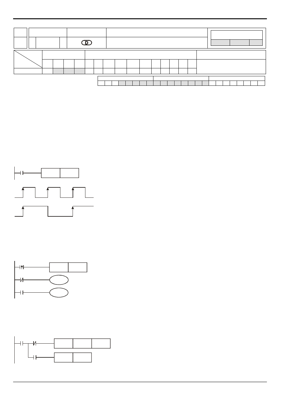
Program Example 1:
When X0 goes from Off to On, Y0 will be On. When X0 goes from Off to On for the second time, Y0 will be Off.
X0
ALTP
Y0
X0
Y0
Program Example 2:
Using a single switch to enable and disable control. At the beginning, M0 = Off, so Y0 = On and Y1 = Off. When X10
switches between On/Off for the first time, M0 will be On, so Y1 = On and Y0 = Off. For the second time of On/Off
switching, M0 will be Off, so Y0 = On and Y1 = Off.
X10
ALT
M0
M0
Y0
M0
Y1
Program Example 3:
Generating flashing. When X10 = On, T0 will generate a pulse every 2 seconds and Y0 output will switch between On
and Off following the T0 pulses.
X10
TMR
T0
ALTP
Y0
K20
T0
T0