1 basic principles of plc ladder diagram – Delta Electronics Programmable Logic Controller DVP-PLC User Manual
Page 22
1 Basic Principles of PLC Ladder Diagram
DVP-PLC Application Manual
1-18
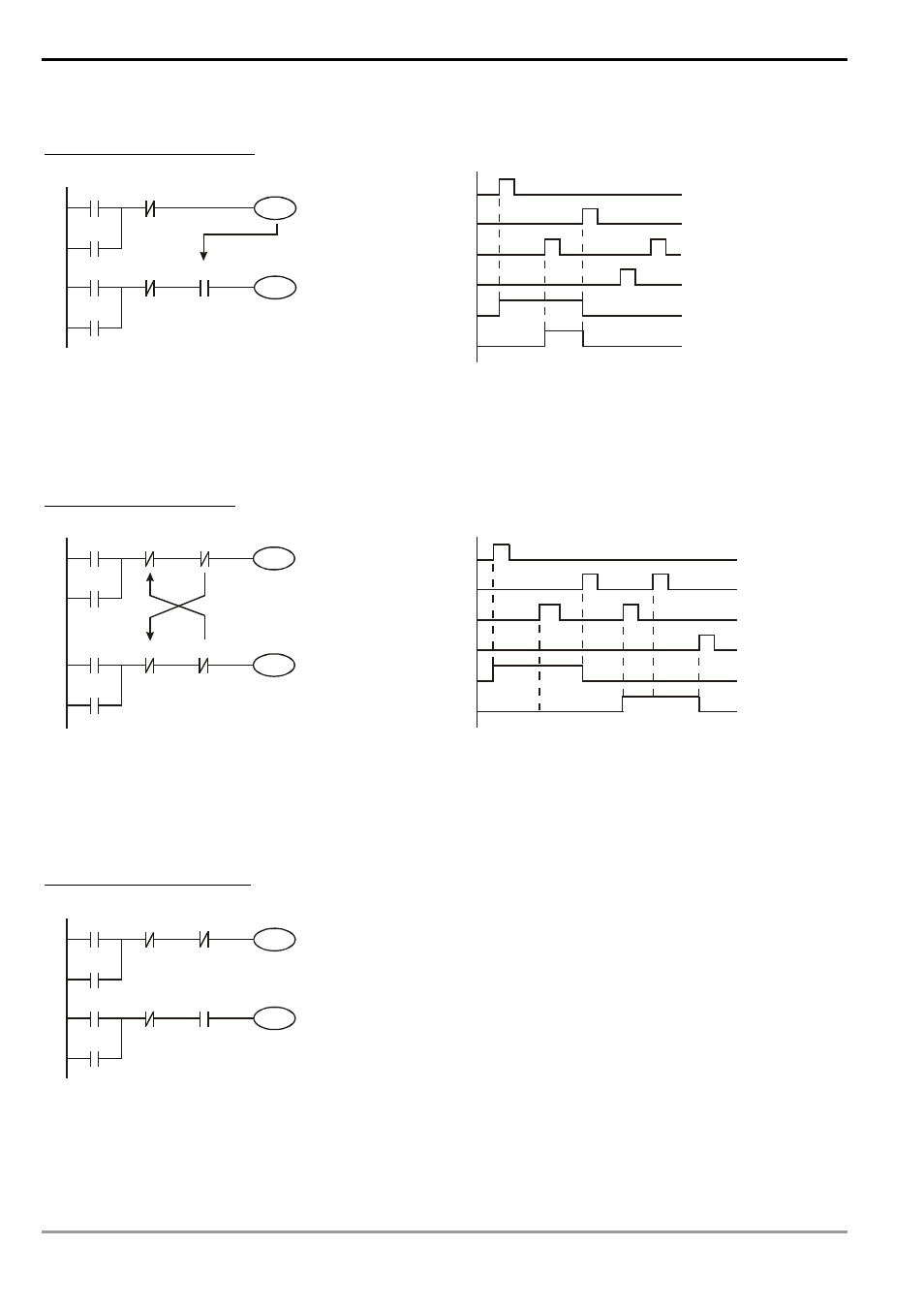
Frequently Used Control Circuit
Example 5: Conditional control
X3
Y1
X1
Y1
X4
Y2
X2
Y2
Y1
X1
X3
X2
X4
Y1
Y2
X1 and X3 enables and disables Y1; X2 and X4 enables and disables Y2, and all are latched. Due to that the
normally open contact of Y1 is connected to the circuit of Y2 in series, Y1 becomes an AND condition for Y2.
Therefore, only when Y1 is enabled can Y2 be enabled.
Example 6: Interlock control
X3
Y1
X1
Y1
X4
Y2
X2
Y2
Y1
Y2
X1
X3
X2
X4
Y1
Y2
Which of the X1 and X2 is first enabled decides either the corresponding output Y1 or Y2 will be enabled first.
Either Y1 or Y2 will be enabled at a time, i.e. Y1 and Y2 will not be enabled at the same time (the interlock). Even X1
and X2 are enabled at the same time, Y1 and Y2 will not be enabled at the same time due to that the ladder diagram
program is scanned from up to down. In this ladder diagram, Y1 will be enabled first.
Example 7: Sequential control
X3
Y1
X1
Y1
X4
Y2
X2
Y2
Y1
Y2
If we serially connect the normally closed contact
of Y2 in example 5 to the circuit of Y1 as an AND
condition for Y1 (as the diagram in the left hand side),
the circuit can not only make Y1 as the condition for Y2,
but also allow the stop of Y1 after Y2 is enabled.
Therefore, we can make Y1 and Y2 execute exactly the
sequential control.