2 functions of devices in dvp-plc – Delta Electronics Programmable Logic Controller DVP-PLC User Manual
Page 54
2 Functions of Devices in DVP-PLC
DVP-PLC Application Manual
2-26
X12
X0
0
1
2
3
4
5
0
X10
Contact X11, M1241
6
7
6
5
4
3
Counting up
Counting down
PV in C241
Contact Y0, C241
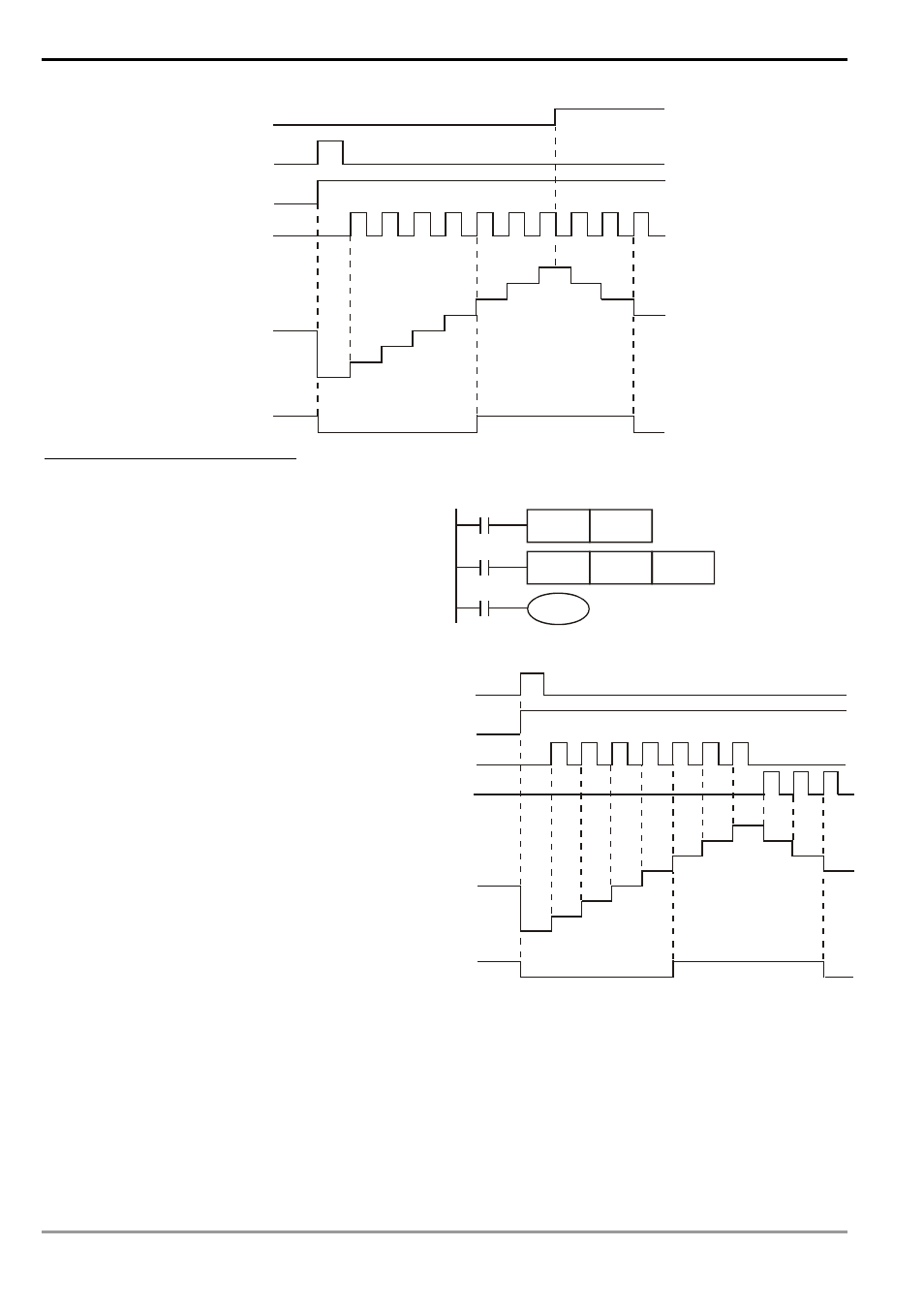
1-phase 2 inputs high-speed counter
Example:
LD
X10
RST C246
LD X11
DCNT C246
K5
LD C246
OUT Y0
C246
Y0
X11
C246
K5
DCNT
C246
RST
X10
1. When X10 is On, RST instsruction will be
executed. The PV in C246 will be cleared to
“0” and the output contact will be reset to be
Off.
2. In C246, when X11 is On and C246 receives
the signals from X0, the PV in the counter will
count up (plus 1) or count down (minus 1).
3. When the counting of C246 reaches SV K5,
the contact of C246 will be On. If there are
still input signals from X0, the counting will
continue.
4. C246 in EH/EH2/SV series MPU has external
input signals to reset X2 and start X3.
X11
0
1
2
3
4
5
0
X10
6
7
6
5
4
3
X1
Counting up
X0
Counting down
PV in
C246
Contact Y0, C246
5. The counting modes (normal frequency or double frequency) of C246 (HHSC0) in EH/EH2/SV series MPU
can be set up by D1225. The default setting is double frequency mode.
6. The external input contact of reset signal of C246 (HHSC0) in EH/EH2/SV series MPU is disabled by M1264.
The external input contact of start signal is disabled by M1265.
7. The internal input contact of reset signal of C246 (HHSC0) in EH/EH2/SV series MPU is disabled by M1272.
The internal input contact of start signal is disabled by M1273.