Delta Electronics Programmable Logic Controller DVP-PLC User Manual
Page 477
9 Application Instructions API 150-199
DVP-PLC Application Manual
9-5
5.
After receiving the data sent back from AC motor drive is completed, PLC will auto-check if the received data
are incorrect. M1140 will be On if there is an error.
6.
If the device address is illegal to a designated communication device, the communication device will respond
with an error message and PLC will store the error code in D1130 and M1141 = On. For example, if 8000H is
illegal to VFD-S, M1141 will be On and D1130 = 2. See user manual of VFD-S for error codes.
7.
After M1140 = On or M1141 = On, PLC will send another correct datum to AC motor drive. If the data sent back
from AC motor drive is correct, M1140 and M1141 will be reset.
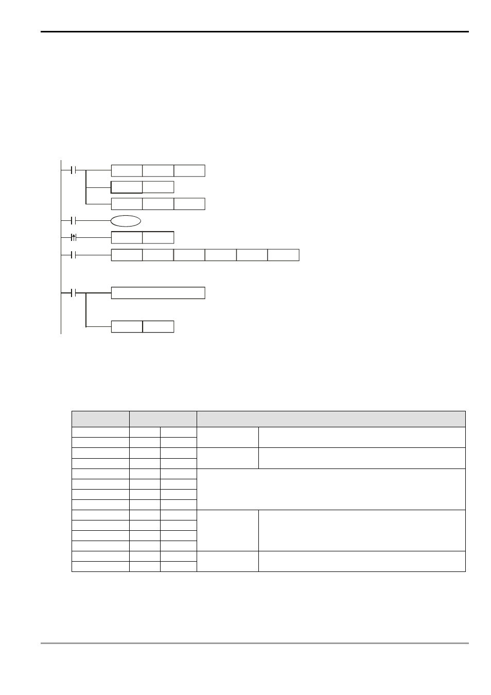
H87
MOV
M1002
D 1120
SET
M1120
K100
MOV
D1129
M1127
RST
M1127
M1143
X10
Set up communication
protocol 9600, 8, E, 1
Retain communication protocol
Communication
time-out 100ms
MODR W
K6
K1
X0
H2000
D 50
K1
Address of
communi-
cat ion
device K1
Function
code K6:
write 1
word datum
Data address
H2000
Register
for st oring
the data
Data length
(word)
SET
X0
M1122
Set up sending request
Process of received data
ASCII mode: the received data will be stored in special registers D1070 ~ D1076 in ASCII format.
Sending/receiving of data is completed. Th e flag is reset.
RTU mode: the received data will be stored in special registers D1 070 ~ D1077 in hex format.
8.
ASCII Mode: When PLC is connected to VFD-S AC motor drive.
PLC
Ö VFD-S, PLC sends: “01 06 0100 1770 71”
VFD-S
Ö PLC, PLC receives: “01 06 0100 1770 71”
Registers for sent data (sending messages)
Register
DATA
Explanation
D1256 Low
‘0’
30 H
ADR 1
D1256 High
‘1’
31 H
ADR 0
Address of AC motor drive: ADR (1,0)
D1257 Low
‘0’
30 H
CMD 1
D1257 High
‘6’
36 H
CMD 0
Instruction code: CMD (1,0)
D1258 Low
‘0’
30 H
D1258 High
‘1’
31 H
D1259 Low
‘0’
30 H
D1259 High
‘0’
30 H
Data Address
D1260 Low
‘1’
31 H
D1260 High
‘7’
37 H
D1261 Low
‘7’
37 H
D1261 High
‘0’
30 H
Data content
The content of register D50 (H1770 = K6,000)
D1262 Low
‘7’
37 H
LRC CHK 1
D1262 High
‘1’
31 H
LRC CHK 0
LRC CHK (0,1) is error check