Delta Electronics Programmable Logic Controller DVP-PLC User Manual
Page 564
9 Application Instructions API 150-199
DVP-PLC Application Manual
9-92
3. Monitor the segment No. that is currently being executed in register D301.
D0
D300
END
X0
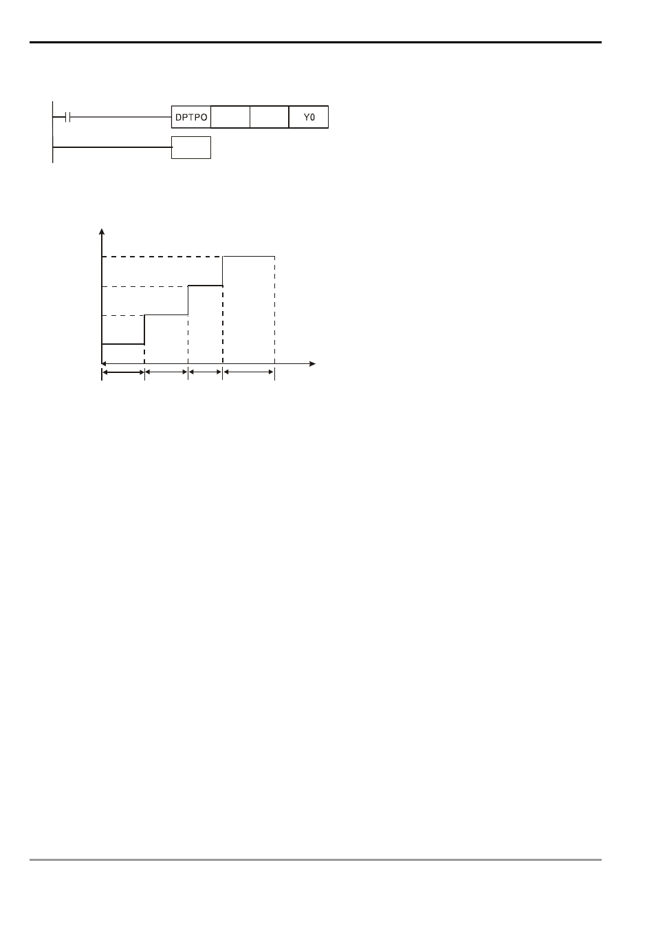
4. The pulse output curve:
Frequency (Hz)
t
t
t
t
1
2
....
60
(D1,D0)
(D3,D2)
(D239,D238)
(D5,D4)
(D237,D236)
....
....
(D7,D6)
Time (S)
Remarks:
1. Flag
explanations:
M1029: On when CH0 (Y0) pulse output is completed.
M1030: On when CH1 (Y2) pulse output is completed.
M1036: On when CH2 (Y4) pulse output is completed.
M1037: On when CH3 (Y6) pulse output is completed.
M1334: When On, CH0 (Y0) pulse output will be forbidden.
M1335: When On, CH1 (Y2) pulse output will be forbidden.
M1520: When On, CH2 (Y4) pulse output will be forbidden.
M1521: When On, CH3 (Y6) pulse output will be forbidden.
M1336: CH0 (Y0) pulse output indication flag
M1337: CH1 (Y2) pulse output indication flag
M1522: CH2 (Y4) pulse output indication flag
M1523: CH3 (Y6) pulse output indication flag
2. Special
register
explanations:
D1336, D1337: Pulse present value register of CH0 (Y0) (D1337 high word, D1336 low word)
D1338, D1339: Pulse present value register of CH1 (Y2) (D1339 high word, D1338 low word)
D1375, D1376: Pulse present value register of CH2 (Y4) (D1376 high word, D1375 low word)
D1377, D1378: Pulse present value register of CH3 (Y6) (D1378 high word, D1377 low word)