Delta Electronics Programmable Logic Controller DVP-PLC User Manual
Page 395
7 Application Instructions API 50-99
D V P - P L C A P P L I C AT I O N M A N U A L
7- 111
If you have no idea how to adjust the parameters, you can select K3 (auto-tuning) and after all the parameters
are adjusted (the control direction will be automatically set as K4), you can modify your parameters to better
ones according to the result of the control.
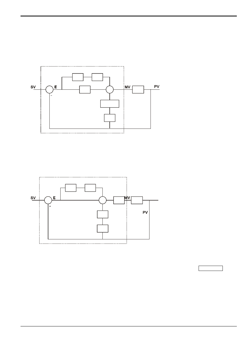
6. Control
diagrams:
G(s)
S
1/S
K
I
K
P
K
D
+
+
+
+
PID instruction is within the dotted-lined area
Diagram 1: + 4 = K0 ~ K2
S
3
In Diagram 1, S is differentiation, referring to “PV – previous PV / sampling time”. 1 / S is integration, referring to
“(previous integral value + error value) × sampling time”. G(S) refers to the device being controlled.
G(s)
S
1/S
1/K
I
K
D
+
+
+
+
1/K
P
PID operation is within the dotted-lined area
Diagram 2: + 4 = K3 ~ K4
S
3
In Diagram 2, 1/K
I
and 1/K
P
refer to “divided by K
I
” and “divided by K
P
”. Due to that this is exclusively for
temperature control, you have to use PID instruction together with GPWM instruction. See Application 3 for
more details.
7. Notes:
a) S
3
+ 6 ~ S
3
+ 13 are only available in SA/SX/SC/EH/EH2/SV series, and ES/EX/SS (v5.7 and above) series
MPU.