1 basic principles of plc ladder diagram – Delta Electronics Programmable Logic Controller DVP-PLC User Manual
Page 20
1 Basic Principles of PLC Ladder Diagram
DVP-PLC Application Manual
1-16
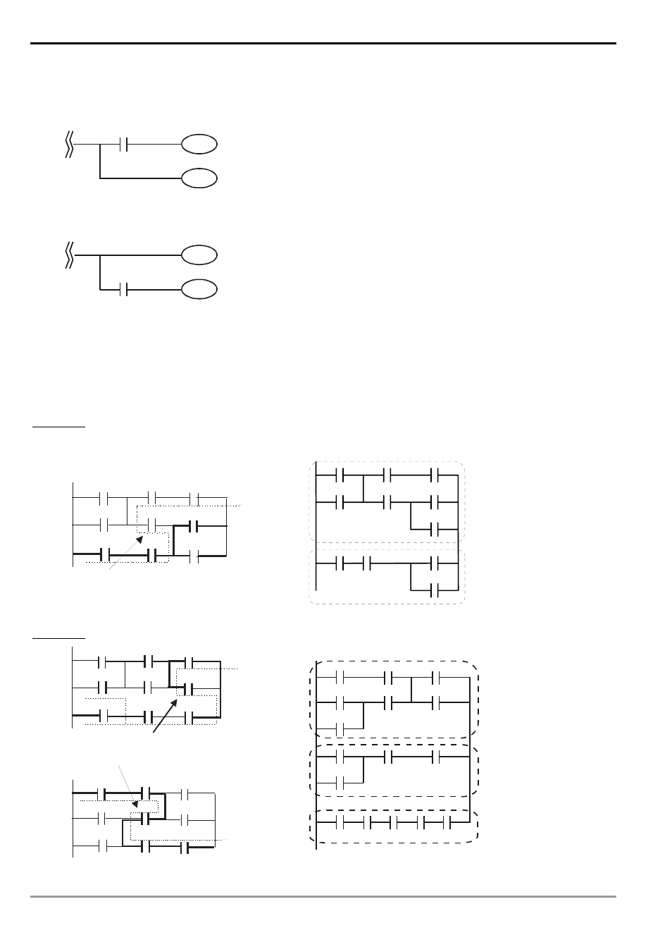
MPS and MPP instruction can be omitted when the multiple outputs in the same horizontal line do not need to
operate with other input devices.
Ladder diagram complied into instruction
MPS
AND X0
OUT Y1
MPP
X0
Y1
Y0
Ø
OUT Y0
Ladder diagram complied into instruction
OUT Y0
AND X0
Y0
Y1
X0
OUT Y1
Correct the circuit of reverse flow
In the following two examples, the diagram in the left hand side is the ladder diagram we desire. However, the illegal
“reverse flow” in it is incorrect according to our definition on the ladder diagram. We modify the diagram into the
diagram in the right hand side.
Example 1
X0
X3
X6
X1
X4
X7
X2
X5
X10
LO OP 1
rever se fl ow
Ö
X0
X1
X2
X3
X4
X5
X10
X6
X7
X5
X10
LOOP1
Example 2
X0
X3
X6
X1
X4
X7
X2
X5
X10
LO OP 1
rever se fl ow
X 0
X 3
X 6
X 1
X 4
X7
X2
X 5
X10
L OO P2
Reverse fl ow
Ö
LOOP1
X0
X1
X2
X3
X4
X5
X6
X3
X7
X10
X6
X0
X1
X7
X10
LOOP
2
X4
- 1x9 Bi-Directional Transceiver Module OPBD-155F2J1R (7 pages)
- Single Mode SFP Transceiver LCP-1250B4MDRx (14 pages)
- LC-1250xxxx Series (10 pages)
- Human Machine Interface DOP-AS Series (329 pages)
- Analog Output Module DVP04DA-S (2 pages)
- DeviceNet Slave Communication Module IFD9502 (2 pages)
- LCP-155B4MSRx (12 pages)
- High-Speed PCI 12-Axis Motion Control Card PCI-DMC-B01 (528 pages)
- Network Device DVP01PU-S (2 pages)
- GBIC-1250D5MR (12 pages)
- SPBD-1250A4Q1RT (10 pages)
- SILM4015 (1 page)
- LCP-8500A4EDR (14 pages)
- 10GBASE-SR SFP+ Optical Transceiver LCP-10G3A4EDR (16 pages)
- LCP-155A4HSRx (11 pages)
- LCP-1250RJ3SR-L (9 pages)
- SILM320L (1 page)
- LCP-1250RJ3SR-S (9 pages)
- SIL530 (1 page)
- Extension Digital I/O Module DOP-EXIO28RAE (1 page)
- DVP Series PLC DVP04TC-H2 (2 pages)
- 1x9 Bi-Directional Transceiver Module OPBD-155F1J1R (7 pages)
- Distribution Box TAP-CN01/02/03 (2 pages)
- LCP-200A4HSR (9 pages)
- Pulse Generation Unit DVP01PU-H2 (2 pages)
- Power Connection Interface VFD-PSD01 (1 page)
- Programmable Logic Controller DVP04DA-H2 (2 pages)
- Single Mode SFP Transceiver LCP-1250B4QDRx (13 pages)
- LCP-155B4JSRx Series (12 pages)
- Series Temperature Controller DTD Series (2 pages)
- Brake Modules BUE Series (2 pages)
- PLC DVP Series DVP-SX (2 pages)
- Digital Keypad / Display ASD-PU-01A (1 page)
- Multimode SFP Transceiver LCP-1250A4FDRx (14 pages)
- HMU1362M (1 page)
- RPA-01 (1 page)
- THMR1395 (1 page)
- SFBD-155F2J1RM (7 pages)
- Program Transfer Module DVP-PCC01 (1 page)
- RTU-DNET (41 pages)
- AC Servo Drive ASDA-AB (37 pages)
- Digital Keypad / Display ASD-PU-01B (1 page)
- HMR1045 (1 page)
- CANopen Communication Module DVPCOPM-SL (2 pages)
- SPBD-1250B4Q1R (10 pages)