Dvp-plc application manual – Delta Electronics Programmable Logic Controller DVP-PLC User Manual
Page 505
9 Application Instructions API 150-199
DVP-PLC Application Manual
9-33
c) Many DRVA instructions can be compiled synchronously in the program, but only one instruction can be
activated whenever the PLC executes the program. For example, if Y10 output has already been activated
by an instruction, other instructions that are also used to activate Y10 output will not be excecuted.
Therefore, the principle of the instruction activation sequence is “first activated, first executed”.
d) When Y10 is activated by DDRVA instruction, the output function of Y10 will be disabled until DDRVAis OFF.
The same rule applies to Y11.
e) Once the instruction is activated, all other parameters cannot be modified until the instruction is disabled.
f) When the instruction is disabled but the output has not yet completed:
M1334 = On indicates that Y10 will stop output immediately.
M1334 = Off indicates that Y10 will decelerate according to the deceleration time till it reaches end frequency
and stop the pulse output.
M1335 corresponds to Y11 output and applies the same rule.
3.
See remarks of DDRVI instruction for more details on the flags.
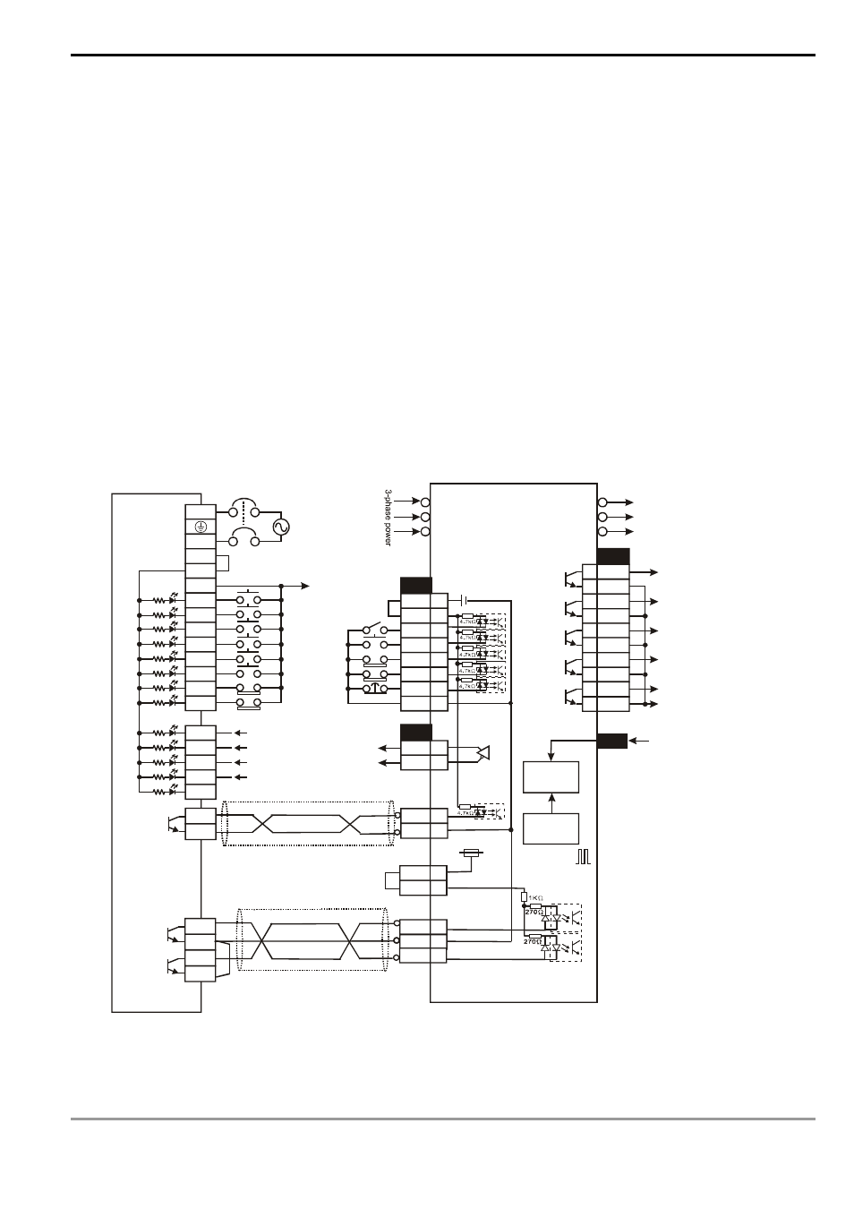
4.
Wiring of DVP-EH series and Delta ASDA servo drive:
/OZ
50
EH MPU
L
N
X0
X1
X2
X3
X4
X5
X6
S/S
Y4
C2
JOG(+)
DI 1:
DI 5:
DI 6:
DI 7:
DI 8:
R
S
T
U
V
W
Delta Servo Drive
COM-
DI 2
+24V
X7
24G
JOG(-)
DO_COM
X10
X11
X12
X13
X14
SRDY
ZSPD
TPOS
ALARM
CN1
CN2
10
45
Y0
C0
Y1
C1
DVP32EH00T
CN1
26
1
2
3
4
5
6
7
DO1+
DO2+
DO3+
DO4+
DO1-
DO2-
DO3-
DO4-
SRDY
ZSPD
HOME
TPOS
220VAC
220VAC
24
27
28 DO5+
DO5-
ALARM
DO_COM
OZ
COM-
PLS
41
47
SIGN
37
PU-HI
VDD
17
35
DC24V
Max. input pulse
frequency: 200kPPS
24V
CN1
VDD
COM+
DI 1
DI 5
DI 6
DI 7
DI 8
17
11
9
33
32
31
30
COM- 45
Single phase
Start
Zero return
Stop
Error reset
Forward limit
Reverse limit
ASDA series
S
e
rv
o
M
o
to
r
Servo start
Servo reset
Forward limit
Reverse limit
Emergency stop
Differential
signal
Clear pulse
Z-phase signal
(zero point signal)
Pulse output
VDD
17
Approx.
Encoder
Error
counter
Electric
gear
Forward/backward direction
Note:
(a)
The parameter setting of Delta ASDA servo drive: