5 categories & use of application instructions – Delta Electronics Programmable Logic Controller DVP-PLC User Manual
Page 200
5 Categories & Use of Application Instructions
DVP-PLC Application Manual
5-8
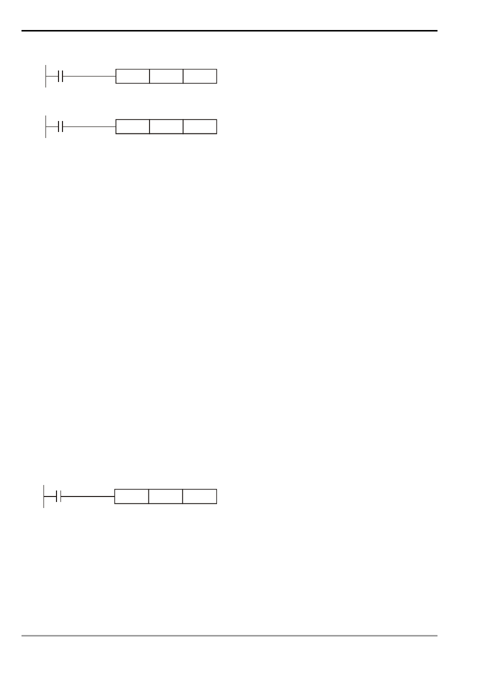
Pulse execution instruction
X0
D10
D12
MOVP
When X0 goes from Off to On, MOVP instruction will be
executed once and the instruction will not be executed
again in the scan period.
Continuous execution instruction
X1
D10
D12
MOV
In every scan period when X1 = On, MOV instruction will
be executed once.
In the two figures, when X0, X1 = Off, the instruction will not be executed, and the content in operand D will
remain unchanged.
Designation of operands
1. Bit devices X, Y, M, and S can be combined into word device, storing values and data for operaions in the form
of KnX, KnY, KnM and KnS in an application instruction.
2. Data register D, timer T, counter C and index register E, F are designated by general operands.
3. A data register is usually in 16 bits, i.e. of the length of 1 register D. A designated 32-bit data register refers to
2 consecutive register Ds.
4. If an operand of a 32-bit instruction designates D0, the 32-bit data register composed of (D1, D0) will be
occupied. D1 is the higher 16 bits; D0 is the lower 16 bits. The same rule also apply to timer T, 16-bit timers
and C0 ~ C199.
5. When the 32-bit counters C200 ~ C255 are used as data registers, they can only be designataed by the
operands of 32-bit instructions.
Format of operand
1. X, Y, M, and S can only On/Off a single point and are defined as bit devices.
2. 16-bit (or 32-bit) devices T, C, D, and registers E, F are defined as word devices.
3. You can place Kn (n = 1 refers to 4 bits. For 16-bit instruction, n = K1 ~ K4; for 32-bit instruction, n = K1 ~ K8)
before bit devices X, Y, M and S to make it a word device for performing word-device operations. For example,
K1M0 refers to 8 bits, M0 ~ M7.
X0
K2M0
D10
MOV
When X0 = On, the contents in M0 ~ M7 will be moved to
bit0 ~ 7 in D10 and bit8 ~ 15 will be set to “0”.