Delta Electronics Programmable Logic Controller DVP-PLC User Manual
Page 424
8 Application Instructions API 100-149
DVP-PLC Application Manual
8-22
API Mnemonic Operands
Function
109
SWRD P
Read Digital Switch
Controllers
ES/EX/SS SA/SX/SC EH/SV
Bit Devices
Word Devices
Program Steps
Type
OP
X Y M S K H
KnX
KnY KnM KnS T
C
D
E
F
D
*
*
*
*
*
*
*
*
SWRD, SWRDP: 3 steps
PULSE 16-bit 32-bit
ES EX SS SA SX SC EH SV ES EX SS SA SX SC EH SV ES EX SS SA SX SC EH SV
Operands:
D
: Device for storing the read value
Explanations:
1. See the specifications of each model for their range of use.
2. Flags: M1104 ~ M1111 (status of digital switch)
3. This instruction stores the value read from digital switch function card into D.
4. The read value is stored in the low byte in D. Every switch has a corresponding bit.
5. When there is no digital function card inserted, the error message C400 (hex) will appear in grammar check.
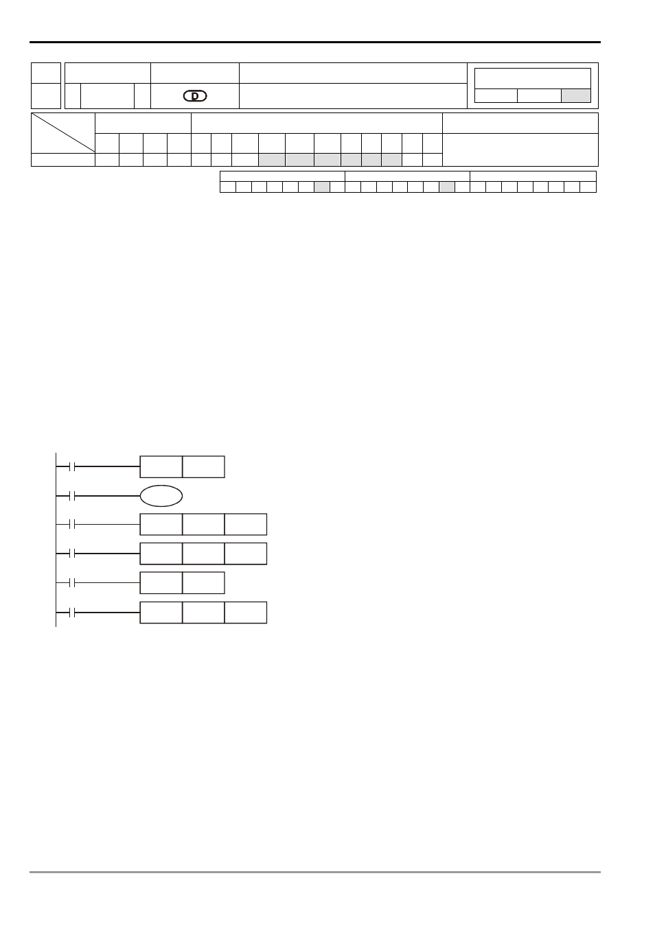
Program Example:
1. There are l 8 DIP switches on the digital switch function card. After the switches are read by SWRD instruction,
the status of each switch will correspond to M0 ~ M7.
M1000
SWRD
K2M0
M0
Y0
M1
MOV
K2M0
D0
M2
CNT
C0
K10
M3
RST
C0
M4
TMR
T0
K100
2. The status of M0 ~ M7 can be executed by each contact instruction.
3. The execution of END instruction indicates that the process of input is completed. REF (I/O refresh) instruction
will be invalid.
4. When SWRD instruction uses the data in digital switch function card, it can read minimum 4 bits (K1Y*, K1M*
or K1S*).
Remarks:
When digital switch function card is inserted, the status of the 8 DIP switches will correspond to M1104 ~ M1111.