Delta Electronics Pulse Generation Unit DVP01PU-H2 User Manual
Warning, Introduction, Specifications
1.
Warning
This instruction sheet provides information on the installation, wiring and trial operation of DVP01PU-H2. For more
detailed information, see “DVP-PLC Application Manual: Special Module”.
DO NOT touch any terminal when the power is switched on. Switch off the power before wiring.
DVP01PU-H2 is an OPEN-TYPE device and therefore should be installed in an enclosure free of airborne dust,
humidity, electric shock and vibration. The enclosure should prevent non-maintenance staff from operating the device
(e.g. key or specific tools are required to oepn the enclosure) in case danger and damage on the device may occur.
DO NOT connect input AC power supply to any of the I/O terminals; otherwise serious damage may occur. Check all
the wiring again before switching on the power.
Introduction
■■■■ Model Explanation and Peripherals
DVP01PU-H2 pulse generation unit is mainly applied to the speed or position control of step or servo drive
system. The maximum output pulse of DVP01PU-H2 can be up to 200kPPS. DVP01PU-H2 is built in with
various route control modes. Through FROM/TO instructions in DVP-EH2 MPU program, the data in
DVP01PU-H2 can be read or written. There are 54 16-bit control registers (CR) in DVP001PU-H2. The
32-bit parameters are composed of 2 continuous CR#.
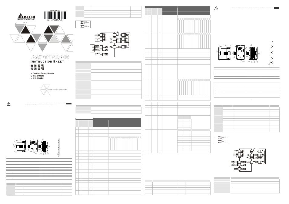
■■■■ Product Profile (Indicators, Terminal Block, I/O Terminals)
Unit: mm
0
V
S
T
A
R
T
D
O
G
L
S
N
A
-
2
4
V
S
/S
B
-
P
G
0
-
C
L
R
-
F
P
-
R
P
-
S
T
O
P
L
S
P
A
+
B
+
P
G
0
+
C
L
R
+
F
P
+
F
P
-
8
○
1
DIN rail (35mm)
○
6
Terminals
○
2
Connection port for extension unit/module
○
7
Mounting hole
○
3
Model name
○
8
I/O terminals
○
4
Status indicators
○
9
Connection port for extension unit/module
○
5
DIN rail clip
■■■■ LED Indicators
POWER : Power indicator, +5V internal power is normal
START : Starting input indicator
LV
: Low voltage indicator (on when the external
STOP : Stopping input indicator
power supply is less than19.5V)
DOG
: DOG input indicator
ERROR : Error indicator (On/Off/flash). Flashes when
FP
: Forward pulse output indicator
CR#44 is not 0.
RP
: Reverse pulse output indicator
LSP
: Right limit input indicator
Φ
A
: MPG A-phase pulse input indicator
LSN
: Left limit input indicator
Φ
B
: MPG A-phase pulse input indicator
PG0
: Zero signal input indicator
CLR
: Clearing signal output indicator
■■■■ I/O Terminal Signals
Type
Terminal
Description
Response feature
Power supply
+24V, 0V
Power input: 24V DC (-15 ~ +20%), Current consumption: 100mA
-
START
Starting input
15ms/50ms
STOP
Stopping input
15ms
LSP/LSN
Right/left limit input
1ms
Φ
A+, ΦA-
MPG A-phase pulse input +, - (differential signal input)
200kHz
Φ
B+, ΦB-
MPG B-phase pulse input +, - (differential signal input)
200kHz
Input
PG0+, PG0- Zero signal input +, - (differential signal input)
1ms
ENGLISH
Input
DOG
2 variations according to different operation modes:
1. DOG signal when in zero return
2. Interruption signal inserted in signal-speed or 2-speed sections
1ms
CLR+, CLR- Clearing signal (clearing signals in the error counter in servo drive)
130ms
FP+, FP-
FP/RP mode: forward pulse output; pulse/direction: pulse output;
A/B phase: A phase output
200kHz
Output
RP+, RP-
FP/RP mode: reverse pulse output; pulse/direction: direction output;
A/B phase: B phase output
200kHz
■■■■ Wiring
Less than
6.8 mm
Less than
6.8 mm
For M3.5
1. Use O-type or Y-type terminals for the I/O wiring as shown in the figure. The torque of
screw at the PLC terminal should be 5 ~ 8 kg-cm (4.3 ~ 6.9 in-lbs).
2. DO NOT place the wirings of input signals, output signals and power supply in the same
wire conduit.
3. Use only 60/75°C copper conductors.
■■■■ I/O Circuit
DVP01PU-H2
START
STOP
LSP
LSN
DOG
S/S
+24V
5-24VDC
+24VDC input
24V
0V
FP+
FP-
RP+
RP-
CLR+
CLR-
A phase
ΦA+
ΦA-
ΦB+
PG0+
PG0-
5-24VDC
PLS
/PLS
SIGN
/SIGN
DI2
COM-
VDD
COM+
17
11
41
43
37
36
10
45
24V
B phase
ΦB-
Delta Servo Drive
ASDA series
Shielding cable
MPG pulse
Specifications
Item
Description
Power supply
24V DC (-15% ~ +20%); Current consumption: 140 ± 30mA, supplied by DVP-EH2 MPU or
other self-prepared power supplier
Max. number of
connected modules/axes
8 modules (axes), which will not occupy any I/O points. DVP-EH2 series MPU is able to
connect to max. a total of 8 extension modules.
Distance
Set up by CR. Range: -2,147,483,648 ~ +2,147,483,647; unit: um, mdeg, 10
-4
inch, Pulse;
multiplications: 10
0
, 10
1
, 10
2
, 10
3
; options: absolute position or relative displacement
Speed
Set up by CR. Range: -2,147,483,648 ~ +2,147,483,647 (10 ~ 200kPPS pulse conversion);
unit: pulse/s, cm/min, 10deg/min, inch/min
External output points
Isolated by photocoupler. LED indicators for all I/O signals.
Output points FP and RP are differential signal (5V).
Output point CLR is transistor NPN open collector (5 ~ 24V DC, less than 20mA).
External input points
Isolated by photocoupler. LED indicators for all I/O signals.
Input points START, STOP, LSP, LSN, DOG are contacts or transistor open collector (24V DC
± 10%, 5±1mA).
Input points ΦA and ΦB are differential or transistor open collector (5 ~ 24V DC, 6 ~ 15mA)
Input points PG0 is differential or transistor open collector (5 ~ 24V DC, 6 ~ 15mA)
Pulse output methods
In 3 modes: Pulse/Dir, FP (CW)/RP (CCW), A/B; by differential output
Position control program
& data exchange with
MPU
Through FROM/TO instructions in DVP-EH2 MPU program, DVP01PU-H2 is able to read and
write the data in the CR. If the data are 32-bit, 2 CRs will be required to process the data.
CR#0 ~ CR#53 are the built-in 16-bit control registers.
When connected to
DVP-PLC MPU in series
The modules are numbered from 0 to 7 automatically by their distance from MPU. No. 0 is the
closest to MPU and No. 7 is the furthest. Maximum 8 modules are allowed to connect to MPU
and will not occupy any digital I/O points.
■■■■ Other Specifications
Environment
Operation/storage
Operation: 0°C ~ 55°C (temperature); 50 ~ 95% (humidity); pollution degree 2.
Storage: -25°C ~ 70°C (temperature); 5 ~ 95% (humidity)
Vibration/shock immunity
International standards: IEC 61131-2, IEC 68-2-6 (TEST Fc)/IEC 61131-2 & IEC 68-2-27
(TEST Ea)
Control Registers
CR#
HW
LW
A
d
d
re
s
s
L
a
tc
h
e
d
A
tt
ri
b
u
te
Content
Setup range
#0
H’4190
○
R
Model name
Set up by the system. DVP01PU-H2 model code = H’6110
#2
#1
H’4191
○
R/W
Number of pulses required
for rotate motor for 1
revolution (A)
Range: 1 ~ +2,147,483,647 PPS/REV
Default = 2,000 pulses/revolution (PLS/REV)
#4
#3
H’4193
○
R/W
Distance the motor rotates
for 1 revolution (B)
Range: 1 ~ +2,147,483,647 unit/REV
Default = 1,000 (unit*1/REV)
b15 b14 b13 b12 b11 b10 b9 b8 b7 b6 b5 b4 b3 b2 b1 b0
#5
H’4195
○
R/W
Parameter setting
Default = H’0000
S
T
O
P
in
p
u
t p
o
la
rit
y
S
T
A
R
T
in
p
u
t p
o
la
rit
y
S
T
A
R
T
re
s
p
o
n
s
e
ti
m
e
A
c
c
e
le
ra
tio
n
c
u
rv
e
o
p
tio
n
s
D
O
G
p
o
la
rit
y
D
O
G
tr
ig
g
e
r m
o
d
e
R
e
v
o
lu
tio
n
d
ire
c
tio
n
Z
e
ro
r
e
tu
rn
d
ire
c
tio
n
L
S
N
in
p
u
t p
o
la
rit
y
L
S
P
in
p
u
t p
o
la
rit
y
P
u
ls
e
o
u
tp
u
t m
e
th
o
d
s
M
u
lti
p
lic
a
tio
n
o
f
p
o
s
iti
o
n
d
a
ta
U
n
it s
e
tti
n
g
#7
#6
H’4196
○
R/W Maximum speed (V
MAX
)
Range: 0 ~ +2,147,483,647 unit*1 (10 ~ 200kPPS pulse
conversion)*2. Default: 200,000 unit*1
#9
#8
H’4198
○
R/W Bias speed (V
BIAS
)
Range: 0 ~ +2,147,483,647 unit*1 (0 ~ 200kPPS pulse
conversion)*2. Default: 0 unit*1
#11 #10
H’419A
○
R/W JOG speed (V
JOG
)
Range: 0 ~ +2,147,483,647 unit*1 (10 ~ 200kPPS pulse
conversion)*2. Default: 5,000 unit*1
#13 #12
H’419C
○
R/W Zero return speed (V
RT
)
Range: 0 ~ +2,147,483,647 unit*1 (10 ~ 200kPPS pulse
conversion)*2. Default: 50,000 unit*1
#15 #14
H’419E
○
R/W
Zero return deceleration
speed (V
CR
)
Range: 0 ~ +2,147,483,647 unit*1 (10 ~ 200kPPS pulse
conversion)*2. Default: 1,000 unit*1
#16
H’41A0
○
R/W
The number of PG0 in
zero return mode (N)
Range: 0 ~ +32,767PLS
Default: 0PLS
#17
H’41A1
○
R/W
The number of pulses in
zero return mode (P)
Range: -32,768 ~ +32,767PLS
Default: 0PLS
#18
H’41A2
○
R/W
Zero return mode
(H MODE)
b0: zero return mode
b1: detecting DOG falling edge in zero return mode
#20 #19
H’41A3
○
R/W Setup of zero point (HP)
Range: 0 ~ ±999,999 unit*1. Default: 0 unit*1
#21
H’41A5
○
R/W Acceleration time (T
ACC
)
Range: 10 ~ +32,767ms. Default: 100ms
#22
H’41A6
○
R/W Deceleration time (T
DEC
)
Range: 10 ~ +32,767ms. Default: 100ms
#24 #23
H’41A7
╳
R/W Target position (I) (P(I))
Range: -2,147,483,648 ~ +2,147,483,647 unit*1
(-2,147,483,648 ~ +2,147,483,647 pulse conversion) *2.
Default: 0 unit*1
#26 #25
H’41A9
╳
R/W Operation speed (I) (V(I))
Range: -2,147,483,648 ~ +2,147,483,647 unit*1 (10 ~
200kPPS pulse conversion)*2. Default: 1,000 unit*1
#28 #27
H’41AB
╳
R/W Target position (II) (P(II))
Range: -2,147,483,648 ~ +2,147,483,647 unit*1
(-2,147,483,648 ~ +2,147,483,647 pulse conversion)*2.
Default: 0 unit*1
CR#
HW
LW
A
d
d
re
s
s
L
a
tc
h
e
d
A
tt
ri
b
u
te
Content
Setup range
#30 #29
H’41AD
╳
R/W Operation speed (II) (V(II))
Range: 0 ~ +2,147,483,647 unit*1 (10 ~ 200kPPS pulse
conversion)*2. Default: 2,000 unit*1
b15 b14 b13 b12 b11 b10 b9 b8 b7 b6 b5 b4 b3 b2 b1 b0
#31
H’41AF
╳
R/W
Operation instruction
Default: H’0000
-
-
C
L
R
o
u
tp
u
t
O
n
/O
ff
C
L
R
s
ig
n
a
l o
u
tp
u
t m
o
d
e
-
C
le
a
r C
P
-
S
o
ftw
a
re
S
T
A
R
T
A
b
s
o
lu
te
p
o
s
iti
o
n
s
e
tu
p
E
n
a
b
lin
g
z
e
ro
re
tu
rn
E
n
a
b
lin
g
J
O
G
-
E
n
a
b
lin
g
J
O
G
+
S
to
p
p
in
g
re
v
e
rs
e
p
u
ls
e
s
S
to
p
p
in
g
fo
rw
a
rd
p
u
ls
e
s
S
o
ftw
a
re
S
T
O
P
E
rr
o
r r
e
s
e
t
b15 b14 b13 b12 b11 b10 b9 b8 b7 b6 b5 b4 b3 b2 b1 b0
#32
H’41B0
╳
R/W
Work mode
Default: H’0001
-
-
-
R
e
s
t t
o
fa
c
to
ry
s
e
tti
n
g
M
A
S
K
s
e
tti
n
g
s
L
S
P
/L
S
N
s
to
p
m
o
d
e
M
a
n
u
a
l P
u
ls
e
G
e
n
e
ra
to
r
ra
n
g
e
S
T
O
P
m
o
d
e
M
a
n
u
a
l P
u
ls
e
G
e
n
e
ra
to
r
in
p
u
t o
p
e
ra
tio
n
V
a
ria
b
le
s
p
e
e
d
o
p
e
ra
tio
n
In
te
rr
u
p
tin
g
2
-s
p
e
e
d
p
o
s
iti
o
n
in
g
o
p
e
ra
tio
n
2
-s
p
e
e
d
p
o
s
iti
o
n
in
g
o
p
e
ra
tio
n
In
te
rr
u
p
tin
g
s
in
g
le
-s
p
e
e
d
p
o
s
iti
o
n
in
g
o
p
e
ra
tio
n
S
in
g
le
-s
p
e
e
d
p
o
s
iti
o
n
in
g
o
p
e
ra
tio
n
#34 #33
H’41B1
╳
R/W Current position CP (PLS)
Range: -2,147,483,648 ~ +2,147,483,647PLS.
Default: 0PLS
#36 #35
H’41B3
╳
R/W Current speed CS (PPS)
Range: 0 ~ +2,147,483,647PPS.Default: 0PPS
#38 #37
H’41B5
╳
R/W
Current position CP
(unit*1)
Range: -2,147,483,648~+2,147,483,647 unit*1
Default: 0 unit*1
#40 #39
H’41B7
╳
R/W Current speed CS (unit*1) Range: 0 ~ +2,147,483,647 unit*
1
. Default: 0 unit*1
#41
H’41B9 ○
R/W
Communica-
tion address setting
Setting up RS-485 communication address. Range: 01 ~
254.
Default: K1
#42
H’41BA ○
R/W
Communication speed
(baud rate) setting
For setting up communication speed:
4,800/9,600/19,200/38,400/ 57,600/115,200bps.ASCII data
format: 7-bit, even bit, 1 stop bit (7, E, 1). RTU data format:
8-bit, even bit, 1 stop bit (8, E, 1).
b0: 4,800bps. b1: 9,600 bps (Default).
b2: 19,200bps. b3: 38,400bps. b4: 57,600bps. b5:
115,200bps
b6 ~ b14: reserved. b15: 0=RTU mode; 1=ASCII mode
(Default).
b15 b14 b13 b12 b11 b10 b9 b8 b7 b6 b5 b4 b3 b2 b1 b0
#43
H’41BB
╳
R/W
Execution status
Default: H’XXXX
-
-
-
-
-
M
P
G
in
p
u
t c
o
u
n
tin
g
d
o
w
n
M
P
G
in
p
u
t c
o
u
n
tin
g
u
p
-
R
o
u
te
p
a
u
s
e
s
P
o
s
iti
o
n
in
g
is
c
o
m
p
le
te
d
E
rr
o
r o
c
c
u
rr
e
d
C
P
v
a
lu
e
o
v
e
rfl
o
w
s
Z
e
ro
re
tu
rn
is
c
o
m
p
le
te
d
R
e
v
e
rs
e
p
u
ls
e
o
u
tp
u
t i
n
p
ro
g
re
s
s
F
o
rw
a
rd
p
u
ls
e
o
u
tp
u
t in
p
ro
g
re
s
s
E
x
e
c
u
tio
n
s
ta
tu
s
#44
H’41BC
╳
R
Error code
See “ Error Code & Troubleshooting” Default: H’0000
#45
H’41BD
╳
R/W
Numerator of MFG
electronic gearing
See explanations below. Default: H’1.
#46
H’41BE
╳
R/W
Denominator of MFG
electronic gearing
See explanations below. Default: H’1.
#48 #47
H’41BF
╳
R/W Input frequency of MPG
Input pulse frequency. Default: 0.
#50 #49
H’41C1
╳
R/W
Accumulated number of
pulses by MPG
Accumulated by the number of pulse input from MPG.
Forward pulse is accumulated by “plus” and reverse pulse
is accumulated by “minus”. The accumulated value will not
be affected by the settings in CR#45 and CR#46. Default:
0.
Set value
Response
speed
5
≧
4ms (default)
4
32ms
3
108ms
2
256ms
#51
H’41C3
╳
R/W
Response speed of MPG
input
1 or 0
500ms
The faster the response speed,
the more synchronous the
instruction pulse output and
MPG pulse input. The slower the
response speed, the more
possible the instruction pulse
output lags behind MPG pulse
input. (Default: 5)
bit #
Status
Description
b0
START input
When START input is On, b0=On.
b1
STOP input
When STOP input is On, b1=On.
b2
DOG input
When DOG input is On, b2=On.
b3
PG0 input
When PG0 input is On, b3=On.
b4
LSP input
When LSP input is On, b4=On.
b5
LSN input
When LSN input is On, b5=On.
b6
A phase input
When A phase input is On,
b6=On.
b7
B phase input
When B phase input is On,
b7=On.
#52
H’41C4
╳
R
Terminal status
b8
CLR output
When CLR output is On, b8=On.
#53
H’41C5 ○ R
Firmware version
Displayed in hex; e.g. V1.00 is indicated as H’0100.
*1: The setting of unit is in accordance with b0 and b1 of CR#5.
*2: The module outputs the maximum pulses if the pulse conversion value exceeds the range and outputs the minimum pulses if the
conversion value falls below the range.
CR#0 ~ CR#53: The corresponding parameter addresses H’4190 ~ H’41C5 are for users to read/write data by
RS-485 communication. When using RS-485, th e user has to separate the module with MPU first.
a. Communication baud rate: 4,800/9,600/19,200/38,400/57,600/115,200bps
b. Modbus ASCII/RTU communication protocols: ASCII data format (7-bit, even bit, 1 stop bit (7, E, 1)); RTU
data format (8-bit, even bit, 1 stop bit (8, E, 1)).
c. Function: H’03 (read register data); H’06 (write 1 word datum to register); H’10 (write many word data to
register)
d. Latched CR should be written by RS-485 communication to stay latched. CR will not be latched if written
by MPU through TO/DTO instruction.
Error Code & Troubleshooting
ERROR LED will be on when hardware malfunction or incorrect parameter settings occur. The error code will
be recorded in CR#44.
Error code
Explanation
Error code
Explanation
H’0000
No error
H’0014
Incorrect V
JOG
H’0001
Incorrect target position (I)
H’0020
FP is forbidden
H’0002
Incorrect target position (II)
H’0021
RP is forbidden
H’0010
Incorrect operation speed (I)
H’0030
Low voltage
H’0011
Incorrect operation speed (II)
H’0080
Hardware error in internal memory
H’0012
Incorrect V
CR
H’0081
Incorrect written in data in internal memory
H’0013
Incorrect V
RT
注意事項
本手冊主要提供 DVP01PU-H2 定位模組安裝、配線回路及試機之參考,有關進一步的使用說明,請參考
DVP-PLC
應用技術手冊【特殊模組篇】。
請勿在上電時觸摸任何端子。實施配線,務必關閉電源。
本機為開放型
(Open Type)
機殼,因此使用者使用本機時,必須將之安裝於具防塵、防潮及免於電擊/衝擊意
外之外殼配線箱內。另必須具備保護措施(如:特殊之工具或鑰匙才可打開)防止非維護人員操作或意外衝
擊本體,造成危險及損壞。
交流輸入電源不可連接於輸入
/
出信號端,否則將造成嚴重的損壞,請在上電之前再次確認電源配線。
產品簡介
說明及週邊裝置
DVP01PU-H2
脈波產生單元主要可應用於步進或伺服驅動系統之速度或位置控制,最高 200kPPS 脈波輸出,
內建多種行程控制模式。透過 DVP-PLC EH2 系列主機程式以指令 FROM/TO 來讀寫模組內之資料,模組內具
有 54 個 CR 暫存器,每個暫存器為 16 bits。32 位元數值參數由兩個連續編號的 CR 所組成。
產品外觀 (指示燈、端子台、端子配置)
尺寸單位:mm
0
V
S
T
A
R
T
D
O
G
L
S
N
A
-
2
4V
S
/S
B
-
P
G
0
-
C
L
R
-
F
P
-
R
P
-
S
T
O
P
L
S
P
A
+
B
+
P
G
0
+
C
L
R
+
F
P
+
F
P
-
8
1
DIN 軌糟 (35mm)
6
端子
2
擴充機/擴充模組連接口
7
固定孔
3
機種名稱
8
端子配置
4
電源、錯誤及轉換指示燈
9
擴充機/擴充模組連接座
5
DIN 軌固定扣
面板指示燈
POWER
:電源指示燈,內部+5V 電源正常
START
:啟動輸入指示燈
LV
:低電壓指示燈,外部電源輸入小於
STOP
:停止輸入指示燈
19.5V
,該指示燈亮
DOG
:近點信號輸入指示燈
ERROR
:錯誤指示燈 (On/Off 閃爍),當 CR#44
FP
:正轉方向脈波輸出指示燈
錯誤編號不為零時動作
RP
:反轉方向脈波輸出指示燈
LSP
:右極限輸入指示燈
ΦA
:手搖輪 A 相脈波輸入指示燈
LSN
:左極限輸入指示燈
ΦB
:手搖輪 B 相脈波輸入指示燈
PG0
:零點訊號輸入指示燈
CLR
:清除信號輸出指示燈
繁體中文
輸入輸出端子信號
種類
端子
說明
響應特性
電源輸入供應 +24V, 0V,
輸入電源,24V DC (-15 ~ +20%),消耗電流 100mA
-
START
啟動輸入
15ms/50ms
STOP
停止輸入
15ms
LSP/LSN
右極限輸入左極限輸入
1ms
ΦA+, ΦA-
手搖輪 A 相脈波輸入+, -(差動信號輸入)
200kHz
ΦB+, ΦB-
手搖輪 B 相脈波輸入+, -(差動信號輸入)
200kHz
PG0+, PG0-
零點訊號輸入+, -(差動信號輸入)
1ms
輸入
DOG
依照運轉模式不同有下列 2 種變化:
1.
原點復歸時為近點信號;2.一段速或二段速插入啟動信號
1ms
CLR+, CLR-
清除信號(Servo 驅動器內部偏差計數器清除信號)
130ms
FP+, FP-
正/反轉模式:正轉方向脈波輸出;脈波/方向:脈波輸出端;
AB
相模式:A 相輸出
200kHz
輸出
RP+, RP-
正/反轉模式:反轉方向脈波輸出;脈波/方向:方向輸出端;
AB
相模式:B 相輸出
200kHz
配線
6.8 mm
以下
6.8 mm
以下
M3.5 用
使
1.
輸出/入配線端請使用 O 型或 Y 型端子,端子規格如左所示。PLC 端子鏍絲扭力為 5 ~ 8 kg-cm
(4.3 ~ 6.9 in-lbs)
。
2.
在配線時請勿請輸入點信號線與輸出點或電源等動力線置於同一線糟內。
3.
只能使用 60/75°C 的銅導線
輸入
/
輸出回路配線
DV P 01PU- H2
S TA RT
STO P
LS P
LS N
DO G
S/ S
+24 V
5-24 V DC
+24 V DC
輸入
24V
0V
FP +
F P-
RP +
RP -
CL R+
CLR -
台達伺服驅動器
隔離 線
手搖輪脈波
A
相
ΦA+
ΦA-
ΦB+
PG0 +
PG0 -
5- 24VD C
PL S
/PL S
SIG N
/SIG N
DI 2
COM -
ASDA 列
系
VD D
COM +
17
11
41
43
37
36
10
45
24V
B
相
ΦB-
規格
項目
說明
電源輸入
24V DC (-15% ~ +20%)
消耗電流 140±30mA;可由 DVP-EH2 主機取得或自備電源供應器。
最大連接台(軸)數
8
台(軸);(不佔任何 I/O 點數,DVP-EH2 主機所能連接特殊擴充機台數總和為 8 台)
距離值
距離設定值由控制暫存器來設定
1.
設定值:-2,147,483,648 ~ +2,147,483,647;2. 單位可選擇:um, mdeg, 10
-4
inch, Pulse
;
3.
可選擇倍率:10
0
, 10
1
, 10
2
, 10
3
;4. 可選擇絕對位置或相對移動量
速度值
速度設定值由控制暫存器來設定
1.
設定值:-2,147,483,648 ~ +2,147,483,647 (10 ~ 200kPPS 的脈波轉換值);
2.
單位可選擇:pulse/s, cm/min, 10deg/min, inch/min