Delta Electronics Programmable Logic Controller DVP-PLC User Manual
Page 283
6 Application Instructions API 00-49
DVP-PLC Application Manual
6-71
M1002
RST
M1081
X10
FLT
D0
D12
X11
DFLT
D0
D20
Program Example 2:
1.
When M1081 = On, the binary floating point value is converted into BIN integer (the decimal is left out).
2.
When X10 = On, D0 and D1 (binary floating point value) are converted into D12 (BIN integer). If D0 (D1) =
H47C35000, the floating point value will be presented as 100,000. Due to that the value is larger than the value
presentable by the 16-bit register D12, the result will be D12 = K32, 767 and M1022 = On.
3.
When X11 = On, D1 and D0 (binary floating point value) are converted into D21 and D20 (BIN integer). If D0 (D1)
= H47C35000, the floating point value will be presented as 100,000. The result will be stored in the 32-bit
register D20 (D21).
M1002
SET
M1081
X10
FLT
D0
D12
X11
DFLT
D0
D20
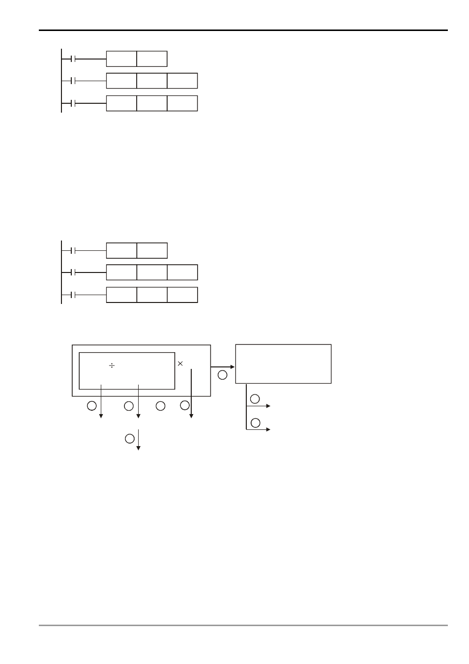
Program Example 3:
Please use this instruction to complete the following operation.
(D10) (X7~X0)
K61.5
16
BIN
-bit
2-digit BCD
(D21,D20)
(D101,D100) (D200) BIN
(D203,D202)
(D301,D300)
(D401,D400)
(D31,D30)
(D41,D40)
1
2
3
4
5
6
7
8
binary floating point
binary floating point
binary floating point
binary floating point
binary floating point
decimal floating point (for
)
monitoring
32
integer
-bit