Delta Electronics Programmable Logic Controller DVP-PLC User Manual
Page 273
6 Application Instructions API 00-49
DVP-PLC Application Manual
6-61
API Mnemonic
Operands
Function
42
ENCO P
Encode
Controllers
ES/EX/SS SA/SX/SC EH/SV
Bit Devices
Word Devices
Program Steps
Type
OP
X Y M S K H
KnX
KnY KnM KnS T C D E F
S
*
*
*
* *
*
*
*
*
D
*
*
*
*
*
n
*
*
ENCO, ENCOP: 7 steps
PULSE 16-bit 32-bit
ES EX SS SA SX SC EH SV ES EX SS SA SX SC EH SV ES EX SS SA SX SC EH SV
Operands:
S
: Source device to be encoded D: Device for storing the encoded result n: Length of encoded bits
Explanations:
1. Range
of
n
when S is a bit device: 1 ~ 8
2. Range
of
n
when S is a word device: 1 ~ 4
3.
ES/EX/SS series MPU does not support E, F index register modification.
4.
See the specifications of each model for their range of use.
5.
The lower “2
n
” bits of S are encoded and the result is stored in D.
6.
If several bits of S are 1, the first bit that is 1 will be processed orderly from high bit to low bit.
7.
If no bits of S is 1, M1067, M1068 = On and D1067 records the error code 0E1A (hex).
8.
This instruction adopts pulse execution instructions (ENCOP)
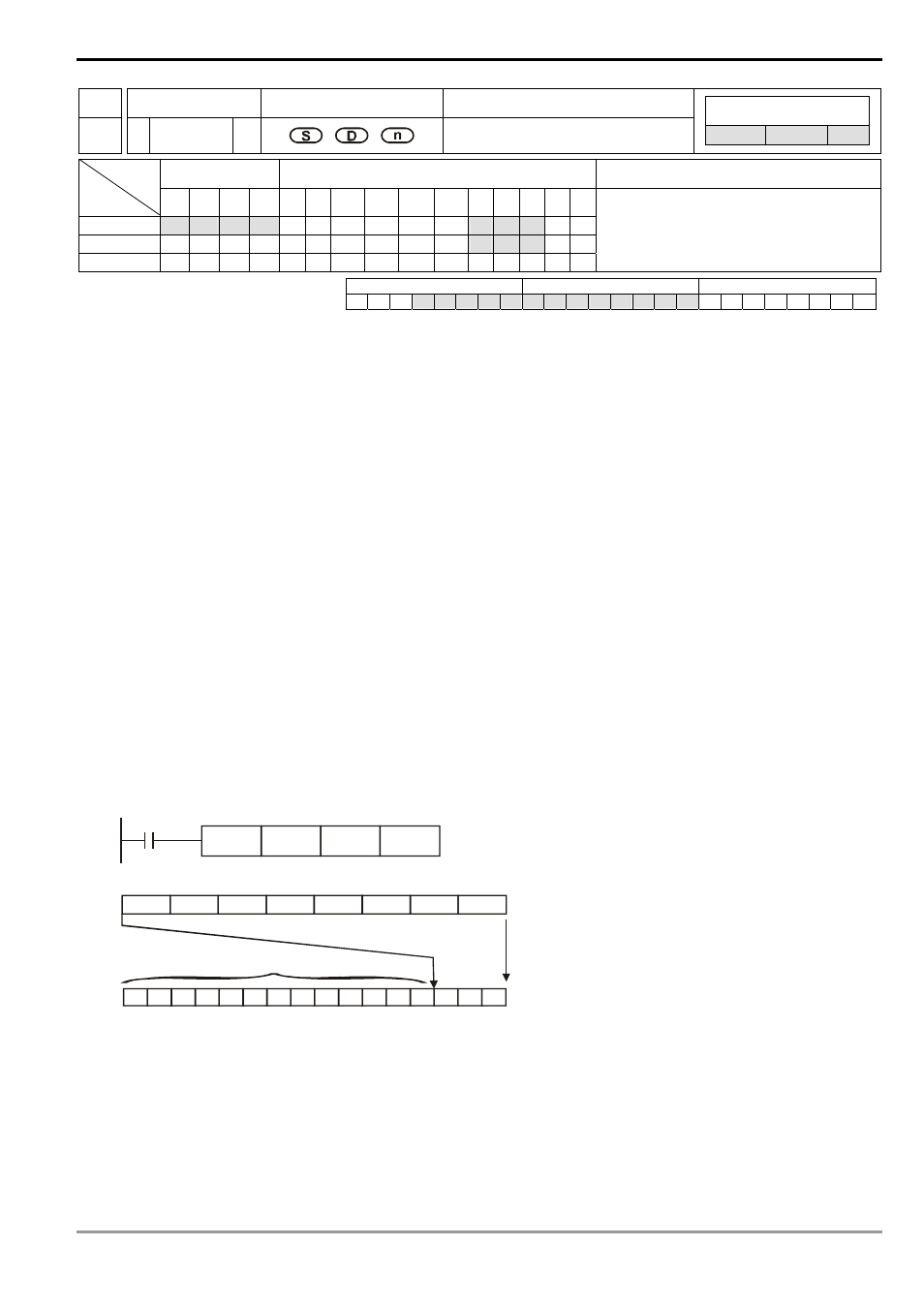
Program Example 1:
1. When S is used as a bit device, n = 1 ~ 8. Errors will occur if n = 0 or n > 8.
2. When
n
= 8, the maximum points to encode is 2
8
= 256 points.
3.
When X10 = Off→On, this instruction will encode the 2
3
bits data (M0 ~ M7) and store the result in the lower 3
bits (b2 ~ b0) of D0. b15 ~ b3 that have not been used in D0 will all become 0.
4.
After the execution of this instruction is completed and X10 turns to Off, the content in D remains unchanged.
ENCOP
M0
K3
D0
X0
0
0
0
0
0
0 0
0
0
0
0
0
1
0
0
1
2
4
b15
b0
D0
1
0
0
0
0
1
0
0
0
7
6
5
4
3
2
1
0
M7
M6
M5
M4
M3
M2
M1
M0
all be 0
Program Example 2:
1. When S is used as a word device, n = 1 ~ 4. Errors will occur if n = 0 or n > 4.
2. When
n
= 4, the maximum points to decode is 2
4
= 16 points.
3.
When X10 = Off→On, this instruction will encode 2
3
bits (b0 ~ b7) in D10 and stores the result in the lower 3 bits
(b2 ~ b0) of D20. b15 ~ b3 that have not been used in D20 will all become 0. b8 ~ b15 of D10 are invalid data.