Delta Electronics Programmable Logic Controller DVP-PLC User Manual
Page 570
9 Application Instructions API 150-199
DVP-PLC Application Manual
9-98
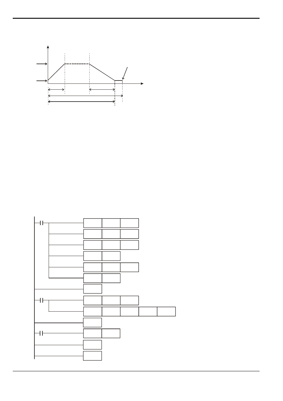
5. Obtain the result of the second execution:
100KHz
D1340
D1348
D1343
X0 Off --> On
Frequency
Y0 stops output
Time
Number
Estimated number of output pulses: 50,000
Actual number of output pulses (D1336, D1337) = K50,020
6. Observe the result of the second execution:
a) The actual output number 50,020 – estimated output number 50,000 = 20
b) 20 x (1/200Hz) = 100ms (idling time)
c) 100ms is an appropriate value. Therefore, set the acceleration time as 250ms and deceleration time as
550ms to complete the design.
Program Example 2:
1. Assume the feedback of the encoder is an A/B phase input and we adopt C251 timing (we suggust you clear it
to 0 before the execution); target number of feedbacks = 50,000; target output frequency = 100KHz; Y0, Y1
(CH0) as output pulses; start/end frequency (D1340) = 200Hz; acceleration time (D1343) = 300ms; deceleration
time (D1348) = 600ms; precentage value (D1198) = 100; current number of output pulses (D1336, D1337) = 0.
2. Write the program codes as follows:
M1002
M1000
M0
I 010
MOV
K100
D1198
K300
D1343
K600
D1348
SET
DMOV
K0
D1336
M1534
RST
C251
EI
DCNT
C251
K100000
DCLLM
K50000 K100000
Y0
FEND
INC
D0
IRET
END
MOV
MOV
C251