Delta Electronics Programmable Logic Controller DVP-PLC User Manual
Page 242
6 Application Instructions API 00-49
DVP-PLC Application Manual
6-30
API Mnemonic Operands
Function
19
D BIN P
Binary
Controllers
ES/EX/SS SA/SX/SC EH/SV
Bit Devices
Word Devices
Program Steps
Type
OP
X Y M S K H
KnX
KnY
KnM KnS T C D E F
S
*
*
*
*
*
*
*
*
*
D
*
*
*
*
*
*
*
*
BIN, BINP: 5 steps
DBIN, DBINP: 9 steps
PULSE 16-bit 32-bit
ES EX SS SA SX SC EH SV ES EX SS SA SX SC EH SV ES EX SS SA SX SC EH SV
Operands:
S
: Source of data D: Conversion result
Explanations:
1. If
S
and D are used in device F, only 16-bit instruction is applicable.
2.
See the specifications of each model for their range of use.
3.
Flags: M1067 (operation error); M1068 (operation error); D1067 (error code)
4.
The content in S (BCD value) is converted into BIN value and stored in D.
5.
Valid range of S : BCD (0 ~ 9,999), DBCD (0 ~ 99,999,999)
6.
Provided the content in S is not a BCD value (in hex and any one of its digits does not fall in the range of 0 ~ 9),
an operation error will occur. M1067, M1068 = On and D1067 records the error code 0E18 (hex).
7.
Constant K and H will automatically be converted into BIN format. Thus, they do not need to adopt this
instruction.
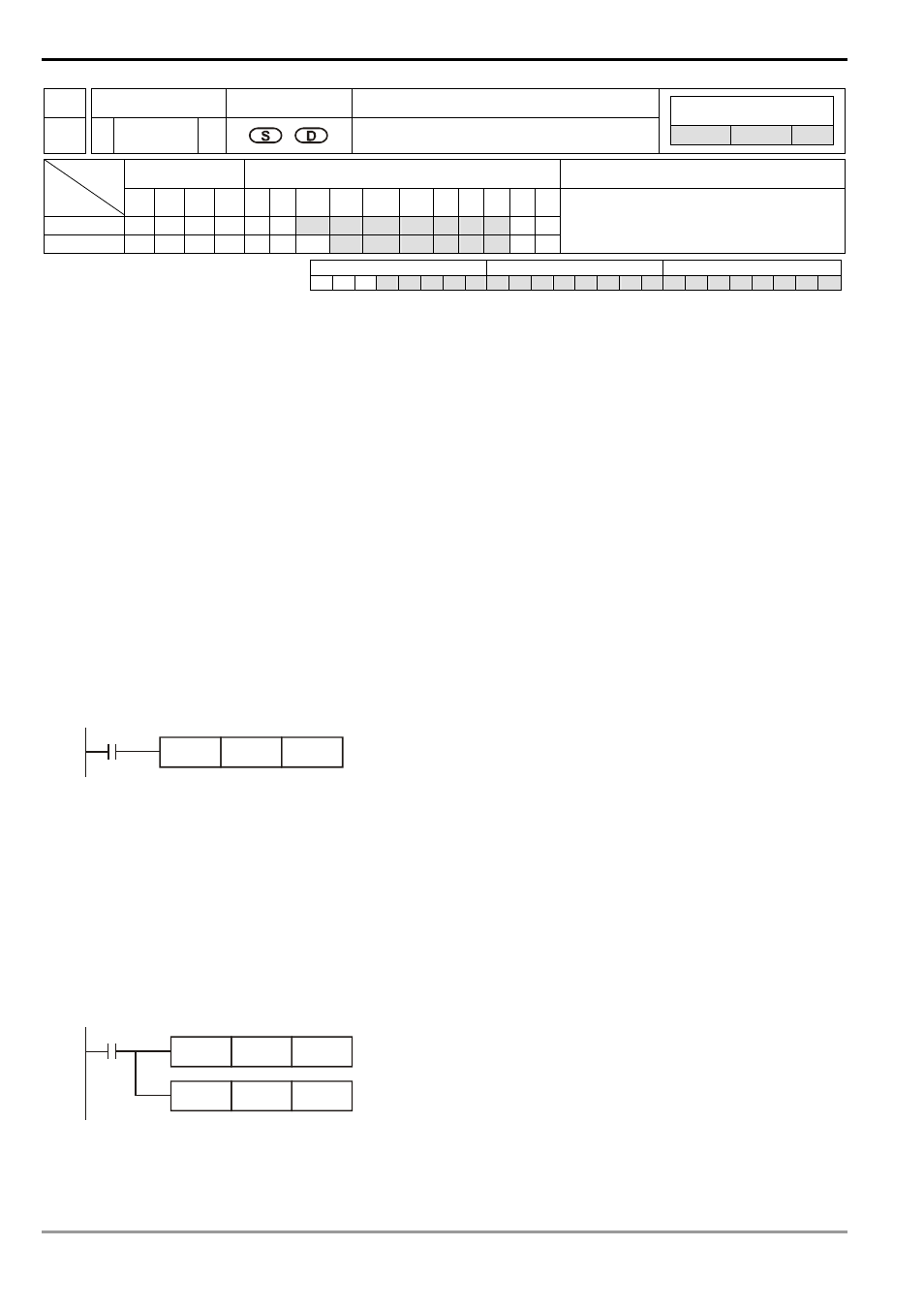
Program Example:
When X0 = On, the BCD value of K1M0 will be converted to BIN value and stored in D10.
X0
BIN
D10
K1M0
Remarks:
Explanations on BCD and BIN instructions:
1.
When PLC needs to read an external DIP switch in BCD format, BIN instruction has to be first adopted to
convert the read data into BIN value and store the data in PLC.
2.
When PLC needs to display its stored data by a 7-segment display in BCD format, BCD instruction has to be
first adopted to convert the data into BCD value and send the data to the 7-segment display.
3.
When X0 = On, the BCD value of K4X0 is converted into BIN value and sent it to D100. The BIN value of D100
will then be converted into BCD value and sent to K4Y20.
X0
BIN
D100
K4X0
BCD
D100
K4Y20