2 functions of devices in dvp-plc – Delta Electronics Programmable Logic Controller DVP-PLC User Manual
Page 47
2 Functions of Devices in DVP-PLC
DVP-PLC Application Manual
2-19
High-speed counters for SC series MPU, total bandwidth: 130KHz
1-phase input
1-phase 2 inputs
2-phase 2 inputs
Type
Input
C235 C236 C237 C238 C239 C240 C241 C242 C243 C244 C245 C246 C247 C249 C250 C251 C252 C254 C255
X0
U/D
U/D
U/D
U
U
U A
A
A
X1 U/D R R D D D B B B
X2
U/D
U/D
R
R R
R
X3
U/D
R S S S
X4
U/D
X5
U/D
X10
U/D
U
A
X11
U/D
D
B
U: Progressively increasing input
A: A phase input
S: Input started
D: Progressively decreasing input
B: B phase input
R: Input cleared
1. The functions of high-speed counters of input points X0 ~ X5 are the same of those in SA/SX series MPU.
2. The maximum frequency of the input points X10 (C243), X11 (C245) and (X10, X11)(C250) of 1-phase input is
100KHz. The total bandwidth of X10 ~ X11 high-speed counting is 130KHz. The maximum input frequency of
C255 (2-phase input X10, X11) is 50KHz.
3. The use of DHSCS instruction together with DHSCR instruction in SA/SX/SC series MPU cannot exceed 6 times.
The use of DHSZ instruction cannot exceed 6 times as well. When DHSCS instruction designates I interruption,
the designated high-speed counter cannot be used in DHSCS, DHSCR and DHSZ instruction.
4. Functions
of
high-speed counters X10 ~ X11 in SC series MPU:
a) When X10 and X11 are set to be 1-phase 1 input or 1-phase 2 outputs, the maximum frequency can reach
100KHz. When set to be 2-phase 2 inputs, the maximum frequency can reach 50KHz.
b) X10 and X11 can be set to be rising-edge or falling-edge counting. X10 is set by D1166 and X11 by D1167. K0:
rising-edge counting; K1: falling-edge counting; K2: rising-/falling-edge counting (only available in X10).
c) Counting up or down of C243 is determined by On/Off status of M1243 anc that of C245 is determined by
On/Off of M1245. Rising-edge and falling-edge countings cannot be performed at the same time. Rising edge
or falling edge of C250 is determined by the content (K0 or K1) in D1166. C255 can only be used in 4 times
frequency counting and rising-edge and falling-edge triggers are not available for C255.
d) When you use C243 or C245, you will not be able to use C250 or C255, and vice versa.
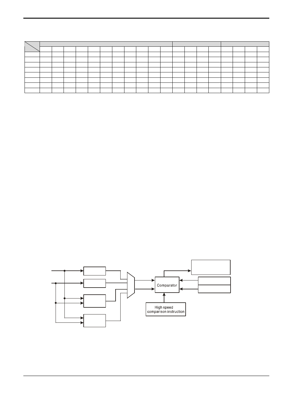
e) High-speed counter and high-speed comparator:
X10
X11
C243
C245
C250
Output reached
comparison value
S V 10
S V 11
C255
f) Explanations on high-speed counter and high-speed comparator:
(i) When DHSCS and DHSCR instructions use new added high-speed counters, they can only use two
groups of SVs in high speed comparison instruction. Assume you have used the comparison instruction
DHSCS D0 C243 Y10, you can only set another group of instruction DHSCR D2 C243 Y10 or DHSCS D4
C245 Y10.