Delta Electronics Programmable Logic Controller DVP-PLC User Manual
Page 388
7 Application Instructions API 50-99
D V P - P L C A P P L I C AT I O N M A N U A L
7-104
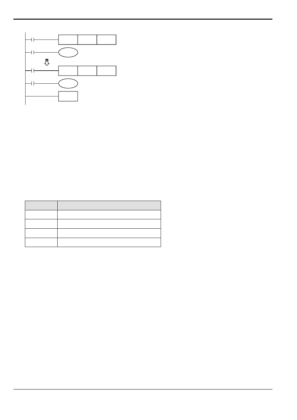
X10
TMR
D100
T0
T0
Y000
X17
TMR
D107
T7
T7
Y007
END
3. Operation of FOR ~ NEXT instruction:
a) In the area between FOR ~ NEXT instruction, FOR designating K8 indicates the loop between FOR ~ NEXT
will be executed repeatedly for 8 times before the next instruction is executed.
b) Between FOR ~ NEXT (INC E), E will be 0, 1, 2, …7 plusing 1. Therefore, the 8 VR rotary switch volumes
will be VR0→D100, VR1→D101, VR2→D102…VR7→D107 and be read to designated registers in order.
Remarks:
1. VR refers to Variable Resister.
2. The 2 points of VR rotary switch built in SA/SC/EH/EH2/SV series MPU can be used together with special D and
special M.
Device
Function
M1178 Enabling
VR0
M1179 Enabling
VR1
D1178 VR0
value
D1179 VR1
value
3. If there is no VR extension card inserted in the PLC, setting up the No. of rotary switches as K2 ~ K7 in VRRD
and VRSC instruction in the program will result in errors in grammar check.
- 1x9 Bi-Directional Transceiver Module OPBD-155F2J1R (7 pages)
- Single Mode SFP Transceiver LCP-1250B4MDRx (14 pages)
- LC-1250xxxx Series (10 pages)
- Human Machine Interface DOP-AS Series (329 pages)
- Analog Output Module DVP04DA-S (2 pages)
- DeviceNet Slave Communication Module IFD9502 (2 pages)
- LCP-155B4MSRx (12 pages)
- High-Speed PCI 12-Axis Motion Control Card PCI-DMC-B01 (528 pages)
- Network Device DVP01PU-S (2 pages)
- GBIC-1250D5MR (12 pages)
- SPBD-1250A4Q1RT (10 pages)
- SILM4015 (1 page)
- LCP-8500A4EDR (14 pages)
- 10GBASE-SR SFP+ Optical Transceiver LCP-10G3A4EDR (16 pages)
- LCP-155A4HSRx (11 pages)
- LCP-1250RJ3SR-L (9 pages)
- SILM320L (1 page)
- LCP-1250RJ3SR-S (9 pages)
- SIL530 (1 page)
- Extension Digital I/O Module DOP-EXIO28RAE (1 page)
- DVP Series PLC DVP04TC-H2 (2 pages)
- 1x9 Bi-Directional Transceiver Module OPBD-155F1J1R (7 pages)
- Distribution Box TAP-CN01/02/03 (2 pages)
- LCP-200A4HSR (9 pages)
- Pulse Generation Unit DVP01PU-H2 (2 pages)
- Power Connection Interface VFD-PSD01 (1 page)
- Programmable Logic Controller DVP04DA-H2 (2 pages)
- Single Mode SFP Transceiver LCP-1250B4QDRx (13 pages)
- LCP-155B4JSRx Series (12 pages)
- Series Temperature Controller DTD Series (2 pages)
- Brake Modules BUE Series (2 pages)
- PLC DVP Series DVP-SX (2 pages)
- Digital Keypad / Display ASD-PU-01A (1 page)
- Multimode SFP Transceiver LCP-1250A4FDRx (14 pages)
- HMU1362M (1 page)
- RPA-01 (1 page)
- THMR1395 (1 page)
- SFBD-155F2J1RM (7 pages)
- Program Transfer Module DVP-PCC01 (1 page)
- RTU-DNET (41 pages)
- AC Servo Drive ASDA-AB (37 pages)
- Digital Keypad / Display ASD-PU-01B (1 page)
- HMR1045 (1 page)
- CANopen Communication Module DVPCOPM-SL (2 pages)
- SPBD-1250B4Q1R (10 pages)