Delta Electronics Programmable Logic Controller DVP-PLC User Manual
Page 495
9 Application Instructions API 150-199
DVP-PLC Application Manual
9-23
API Mnemonic
Operands
Function
157
D PLSV
Adjustable Speed Pulse Output
Controllers
ES/EX/SS SA/SX/SC EH/SV
Bit Devices
Word Devices
Program Steps
Type
OP
X Y M S K H
KnX KnY KnM KnS T
C
D
E
F
S
*
*
*
*
*
*
*
*
*
*
*
D
1
*
D
2
*
*
*
PLSV: 7 steps
DPLSV: 13 steps
PULSE 16-bit 32-bit
ES EX SS SA SX SC EH SV ES EX SS SA SX SC EH SV ES EX SS SA SX SC EH SV
Operands:
S: Pulse output frequency D
1
: Pulse output device (please use transistor output module) D
2
: Output device for
the signal of rotation direction
Explanations:
1.
See remarks for the setting range of S, D
1
and D
2
.
2.
Flag: see remarks of API 155 ABSR and API 158 DDRVI for more details.
3.
S is the designated pulse output frequency. The 16-bit instruction can designate its range 0 ~ +32,767Hz, 0 ~
-32,768Hz. The ranges designated by 32-bit instruction are 0 ~ +200,000Hz and 0 ~ -200,000Hz. “+/-” signs
indicate forward/backward directions. During the pulse output, the frequency can be changed, but not the
frequencies of different directions.
4.
D
1
is the pulse output device. EH series MPU can designate Y0 and Y2 and EH2/SV series MPU can designate
Y0, Y2, Y4 and Y6.
5.
The operation of D
2
corresponds to the “+” or “-“ of S. When S is “+”, D
2
will be On; when S is “-“, D
2
will be Off.
6.
PLSV instruction does not have settings for acceleration and deceleration. Please use API 67 RAMP for the
acceleration and deceleration of pulse output frequency.
7.
During the pulse output executed by PLSV instruction, the drive contact turning Off will result in the immediate
stop of the output without going through a deceleration.
8.
When the absolute value of the input frequency during the execution of DPLSV is bigger than 200KHz, the
output will operate at 200KHz.
9.
For EH/EH2/SV series MPU, D1222, D1223, D1383 and D1384 are the time differences sent between the
direction setup signal and pulse output points of CH0, CH1, CH2 and CH3.
10. For EH/EH2/SV series MPU, M1305, M1306, M1532 and M1533 are the flags of the direction signals of CH0,
CH1, CH2 and CH3. When S is “+”, the output will operate towards a forward direction and the flag will go Off.
When S is “-“, the output will operate towards a backward direction and the flag will go On.
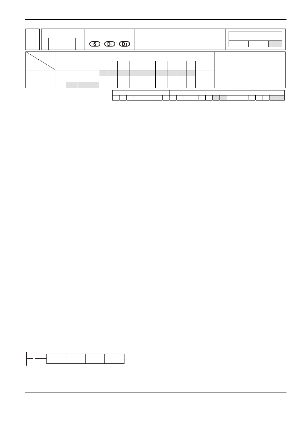
Program Example:
When M10 = On, Y0 will output pulses at 20KHz. Y5 = On indicates forward pulses.
M10
PLSV
K20000
Y0
Y5