Delta Electronics Programmable Logic Controller DVP-PLC User Manual
Page 374
7 Application Instructions API 50-99
D V P - P L C A P P L I C AT I O N M A N U A L
7-90
Fixed as END Hi = CR (0DH), END Lo = LF (0AH)
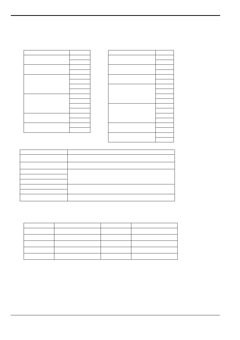
For example: Read 2 continuous data stored in the registers of the driver at address 01H (see the table below).
The start register is at address 2102H.
Inquiry message:
Responding message:
STX
‘: ’
STX
‘: ’
‘0’
‘0’
Address
‘1’
Address
‘1’
‘0’
‘0’
Function code
‘3’
Function code
‘3’
‘2’
‘0’
‘1’
Number of data
(counted by byte)
‘4’
‘0’
‘1’
Start address
‘2’
‘7’
‘0’
‘7’
‘0’
Content in start address
2102H
‘0’
‘0’
‘0’
Number of data
(counted by words)
‘2’
‘0’
‘D’
‘0’
LRC checksum
‘7’
Content of address
2103H
‘0’
CR
‘7’
END
LF
LRC check
‘1’
CR
END
LF
In RTU mode (M1143 = On)
START
See the following explanation
Address
Communication address: In 8-bit binary
Function
Function code: In 8-bit binary
DATA (n-1)
…….
DATA 0
Data:
n × 8-bit data
CRC CHK Low
CRC CHK High
CRC checksum:
16-bit CRC consists of 2 8-bit binary
END
See the following explanation
START:
For ES/EX/SS/SA/SX series MPU, no input signal can be ≥ 10ms.
See the table below for EH/EH2/SV series MPU:
Baud rate(bps) RTU timeout timer (ms) Baud rate (bps) RTU timeout timer (ms)
300 40 9,600 2
600 21
19,200 1
1,200 10 38,400 1
2,400 5 57,600 1
4,800 3 115,200 1
Address:
00H: Broadcasting to all drivers
01H: To the driver at address 01
0FH: To the driver at address 15
10H: To the driver at address 16…. And so on, maximum to the driver at address 254 (FE H)
Function code:
03H: Read contents of many registers