2 functions of devices in dvp-plc – Delta Electronics Programmable Logic Controller DVP-PLC User Manual
Page 61
2 Functions of Devices in DVP-PLC
DVP-PLC Application Manual
2-33
interruptions are I130 and I140. You can also set up that the interruption signal is sent out after the last pulse is
sent out by enabling flags M1340 and M1341. The corresponding interruptions are I110 and I120.
5. Communication
interruption:
I150: When the communication instruction RS is being used, you can send out interruption request when the
program receives a specific word by interruption I150. The specific word is set up in the low byte of D1168. This
function can be adopted when the PLC receives data of different length during the connection with the
communication device. Set up the end word in D1168 and write the interruption subroutine I150 and when the
PLC receives this end word, the program will execute I150.
I160: RS instruction sends out interruption request when receiving a specific length of data. When the data
received equals the low byte of D1169, I160 will be triggered. When D1169 = 0, I160 will not be triggered.
I170: In Slave mode, interruption I170 will be generated when the data receiving is completed. Normally when the
communication terminal of the PLC is in Slave mode, PLC will not immediately process the communication data
entered but process it after the END is executed. Therefore, when the scan time is very long and you need the
communication data to be processed immediately, you can use interruption I170 for this matter.
6. Frequency
measurement
card triggered interruption:
I180: When the PLC sets up the frequency measurement card in mode 1 (pulse cycle measurement) and mode 3
(pulse number counting) by M1019 and D1034, I180 will be supported as well.
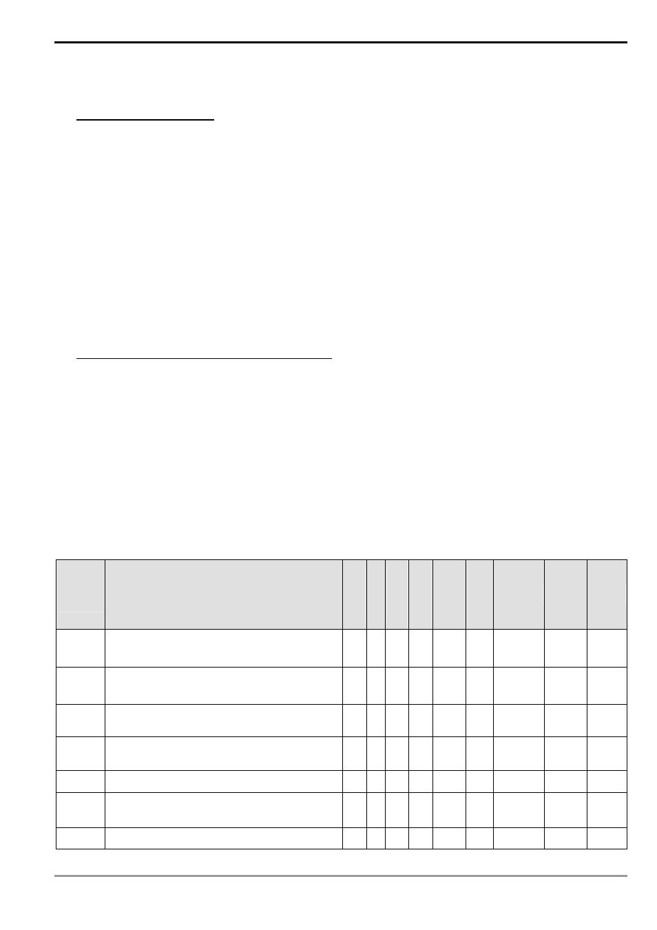
2.10 Special Auxiliary Relays and Special Data Registers
The types and functions of special auxiliary relays (special M) and special data registers (special D) are listed in the
table below. Please be noted that some devices of the same No. may bear different meanings in different series
MPUs. Special M and special D marked with “*” will be further illustrated in the 2.11. Columns marked with “R” regers
to “read only”, “R/W” refers to “read and write”, “-“ refers to the status remains unchanged and “#” refers to the system
will set it up according to the status of the PLC.
Special
M
Function
ES
EX
SS
SA
SX
SC
EH
EH2
SV
Off
Ø
On
STOP
Ø
RUN
RUN
Ø
STO
P
Attribute Latched Default
M1000* Monitoring normally open contact (A)
○
○
○
Off
On
Off R NO Off
M1001* Monitoring normally closed contact (B)
○
○
○
On
Off
On R NO On
M1002* Enabling positive pulses (On when RUN)
○
○
○
Off
On
Off R NO Off
M1003* Enabling negative pulses (Off when RUN)
○
○
○
On
Off
On R NO On
M1004* On when syntax errors occur
○
○
○
Off
Off
- R NO
Off
M1005*
Password of data backup memory card and
password of MPU do not match
╳
╳
○
Off
- - R NO Off
M1006* Data backup memory card has not been initialized
╳
╳
○
Off
- - R NO Off