2 functions of devices in dvp-plc – Delta Electronics Programmable Logic Controller DVP-PLC User Manual
Page 38
2 Functions of Devices in DVP-PLC
DVP-PLC Application Manual
2-10
X0
X10
Y0
Y0
1
2
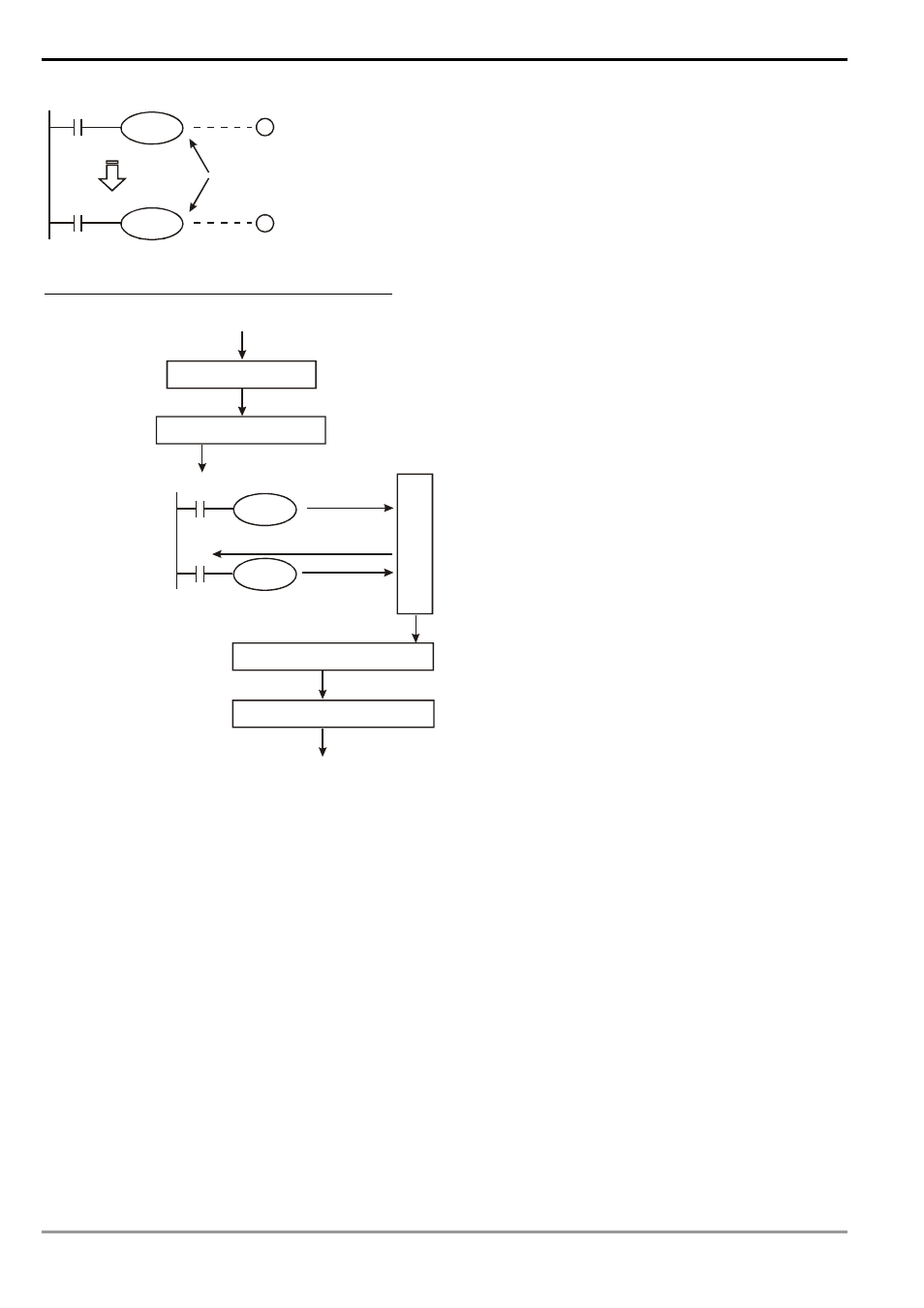
Y0 is repeated
The output of Y0 will be determined by circuit 2, i.e. On/Off of X10 will
determine the output status of Y0.
The Handling Process of PLC Program (Batch I/O)
X0
Y0
Y0
M0
X input
Input terminal
Read into memory
Input signal memory
D
e
vi
ce
M
e
m
o
ry
Read X0 status from memory
Write in Y0 status
Read Y0 status from memory
Write in M0 status
Regenerate output
Program processing
Regenerate input signal
Output
Y output
Output terminal
Output latched memory
Regenerate input signal
1. Before the execution of the program, PLC reads the
On/Off status of the external input signals into the
input signal memory at a time.
2. The On/Off status of the input signal during the
execution of the program will not change the signal
status in the input signal memory. The new On/Off
status will be read in in the next scan.
3. There will be approximately a 10ms delay from the
On→Off or Off→On changes to the status being
recognized by the contact in the program. The delay
time may be affected by the scan time in the
program.
Program processing
After the PLC reads the On/Off status of every input
signal in the input signal memory, it will start to execute
every instruction in the program in order starting from
address 0. The execution result (On/Off of every output
coil) will be stored in order into the device memory.
Regenerate output
1. When the program executes to END instruction, it
will send the On/Off status of Y in the device memory
to the output latched memory. The output latched
memory is the coil of the output relay.
2. There will be a 10ms delay from OnÆOff or OffÆOn
of the relay coil to the On/Off status of the contact.
3. There will be a 10 ~ 20us delay from OnÆOff or
OffÆOn of the transistor module to the On/Off status
of the contact.