Delta Electronics Programmable Logic Controller DVP-PLC User Manual
Page 482
9 Application Instructions API 150-199
DVP-PLC Application Manual
9-10
API Mnemonic
Operands
Function
151
PWD
Detection of Input Pulse Width
Controllers
ES/EX/SS SA/SX/SC EH/SV
Bit Devices
Word Devices
Program Steps
Type
OP
X
Y M S K H KnX KnY KnM KnS T
C D
E
F
S
*
D
*
PWD: 5 steps
PULSE 16-bit 32-bit
ES EX SS SA SX SC EH SV ES EX SS SA SX SC EH SV ES EX SS SA SX SC EH SV
Operands:
S: Source device D: Destination device for storing the detected result
Explanations:
1. Range
of
S: X10 ~ X17
2. Range
of
D: D0 ~ D999, occupying 2 consecutive devices. Can only be used once in the program.
3.
PWD instruction is for detecting the time span of output signals from X10 ~ X17; the valid frequency range is 1
~1KHz. When M1169 = On, the instruction will detect the time span of the continuous rising edge and falling
edge of the input signals (time unit: 100us). When M1169 = On, the instruction will detect the time span of 2
continuous rising edges of the input signals (time unit: 1us). It cannot designate the same X10 ~ X17 as does
DCNT and ZRN instructions.
4.
D occupies two continuous devices. The longest detectable time is 21,474.83647 seconds, about 357.9139
minutes or 5.9652 hours.
5.
There is no limitation on the times of using this instruction. However, only one instruction can be executed at a
time.
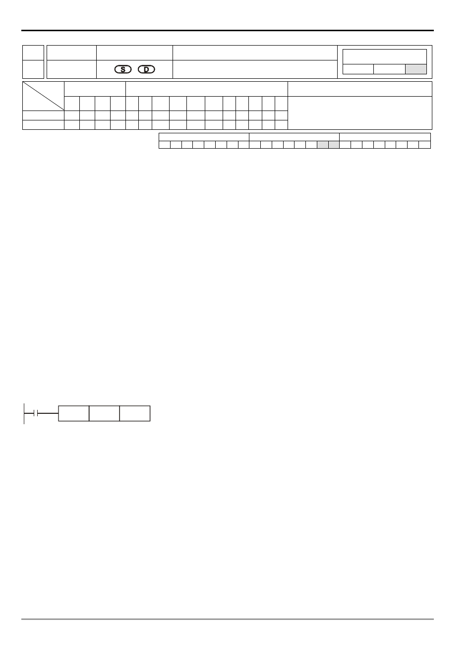
Program Example:
When X0 = On, record the time span of X10 = On and store it in D1 and D0.
X0
PWD
X10
D0