Delta Electronics Programmable Logic Controller DVP-PLC User Manual
Page 316
7 Application Instructions API 50-99
D V P - P L C A P P L I C AT I O N M A N U A L
7-32
API Mnemonic
Operands
Function
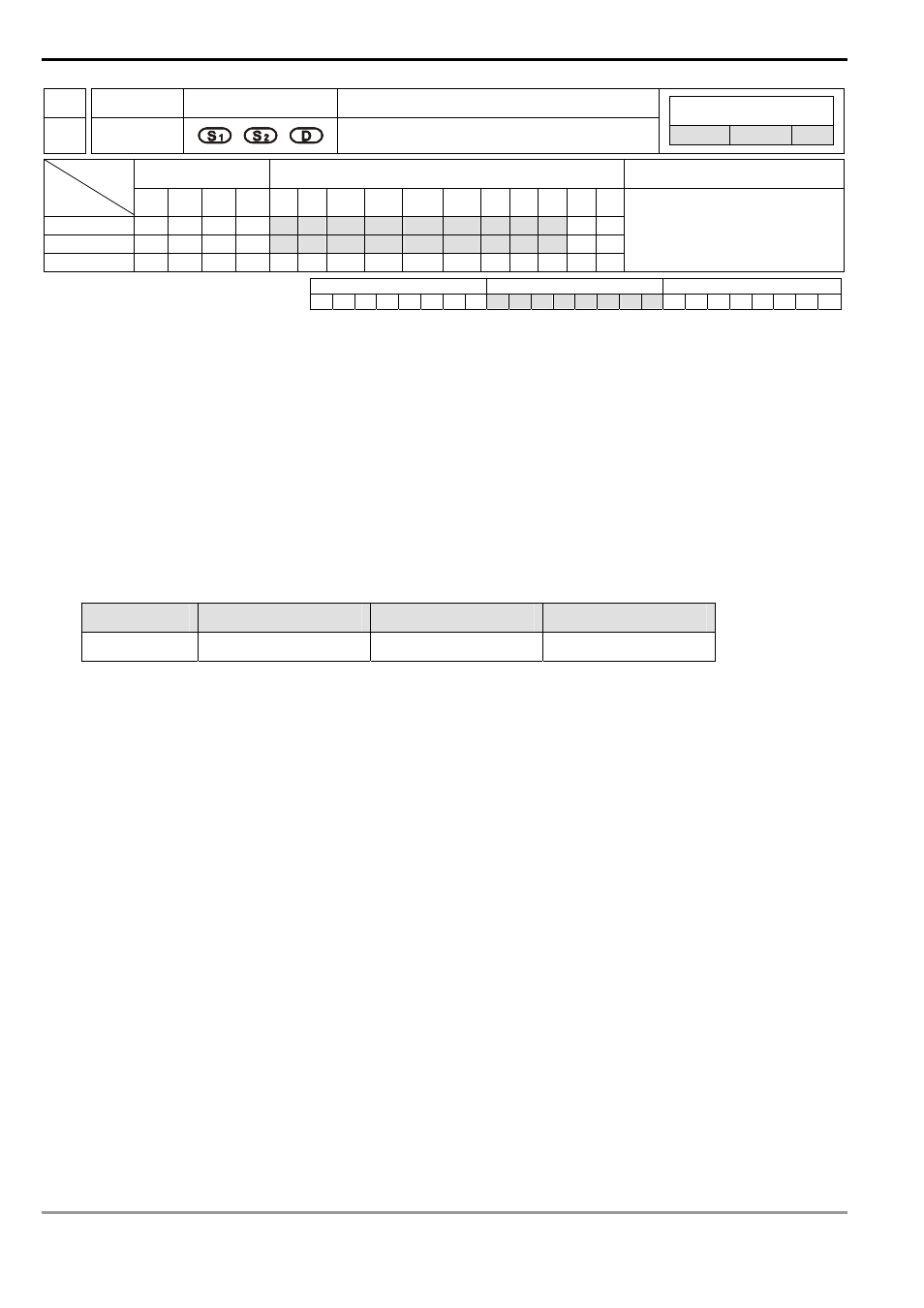
58
PWM
Pulse Width Modulation
Controllers
ES/EX/SS SA/SX/SC EH/SV
Bit Devices
Word Devices
Program Steps
Type
OP
X Y M S K H
KnX
KnY KnM KnS T
C
D
E
F
S
1
*
*
*
*
*
*
*
*
*
*
*
S
2
*
*
*
*
*
*
*
*
*
*
*
D
*
PWM: 7 steps
PULSE 16-bit 32-bit
ES EX SS SA SX SC EH SV ES EX SS SA SX SC EH SV ES EX SS SA SX SC EH SV
Operands:
S
1
: Pulse output width S
2
: Pulse output period D: Pulse output device (please use transistor output module)
Explanations:
1.
S
1
≤ S
2
.
2.
See the specifications of each model for their range of use.
3.
In ES/EX/SS series MPU, PWM instruction can only be used once in the program.
4.
Flags: See remarks for more details.
5. Range
of
S
1
: (t) 0 ~ 32,767ms.
6. Range
of
S
2
: (T) 1 ~ 32,767ms (but S
1
≤ S
2
).
7.
D
for all series MPU:
MPU
ES/EX/SS/SA/SX/SC
EH
EH2/SV
Output point
Y1
Y0, Y2
Y0, Y2, Y4, Y6
8.
When PWM instruction is used in the program, its outputs cannot be the same as those of API 57 PLSY and API
59 PLSR.
9.
PWM instruction designates the pulse output width in S
1
and pulse output period in S
2
and outputs from output
device D.
10. For SA/SX/SC series MPU, When, S
1
≤ 0 or S
2
≤ 0 or S
1
> S
2
, there will be operational errors (M1067 and
M1068 will not be On), and there will be no output from the pulse output device. When S
1
= S
2
, the pulse output
device will keep being On.
11. For EH/EH2/SV series MPU, When, S
1
< 0 or S
2
≤ 0 or S
1
> S
2
, there will be operational errors (M1067 and
M1068 will be On), and there will be no output from the pulse output device. When S
1
= 0, M1067 and M1068
will not be On and there will be no output from the pulse output device. When S
1
= S
2
, the the pulse output
device will keep being On.
12. S
1
and S
2
can be changed when PWM instruction is being executed.
13. For SA/EH series MPU, there is no limitation on the times using this instruction in the program. However, for
SA/SX/SC/EH series MPU, two instructions are allowed to be executed at the same time; for EH2/SV series
MPU, four instructions are allowed to be executed at the same time.