Delta Electronics Programmable Logic Controller DVP-PLC User Manual
Page 437
8 Application Instructions API 100-149
DVP-PLC Application Manual
8-35
API Mnemonic
Operands
Function
124
D EXP P
Exponent of Binary Floating Point
Controllers
ES/EX/SS SA/SX/SC EH/SV
Bit Devices
Word Devices
Program Steps
Type
OP
X Y M S K H
KnX KnY KnM KnS T
C
D
E
F
S
*
*
*
D
*
DEXP, DEXPP: 9 steps
PULSE 16-bit 32-bit
ES EX SS SA SX SC EH SV ES EX SS SA SX SC EH SV ES EX SS SA SX SC EH SV
Operands:
S
: Device for operation source D: Device for operation result
Explanations:
1. See the specifications of each model for their range of use.
2. Flags: M1020 (zero flag); M1021 (borrow flag); M1022 (carry flag)
3. e = 2.71828 as the base and S as exponent for EXP operation: EXP
[
D
+1, D
]
=[S +1, S]
4. Both positive and negative values are valid for S. When designating D registers, the data should be 32-bit and
the operation should be performed in floating point system. Therefore, S should be converted into a floating
point value.
5. The content in D = e
S
; e = 2.71828,
S
= designated source data
6. If the absolute value of the result > maximum floating point available, the carry flag M1022 = On.
7. If the absolute value of the result < minimum floating point available, the borrow flag M1021 = On.
8. If the result = 0, the zero flag M1020 = On.
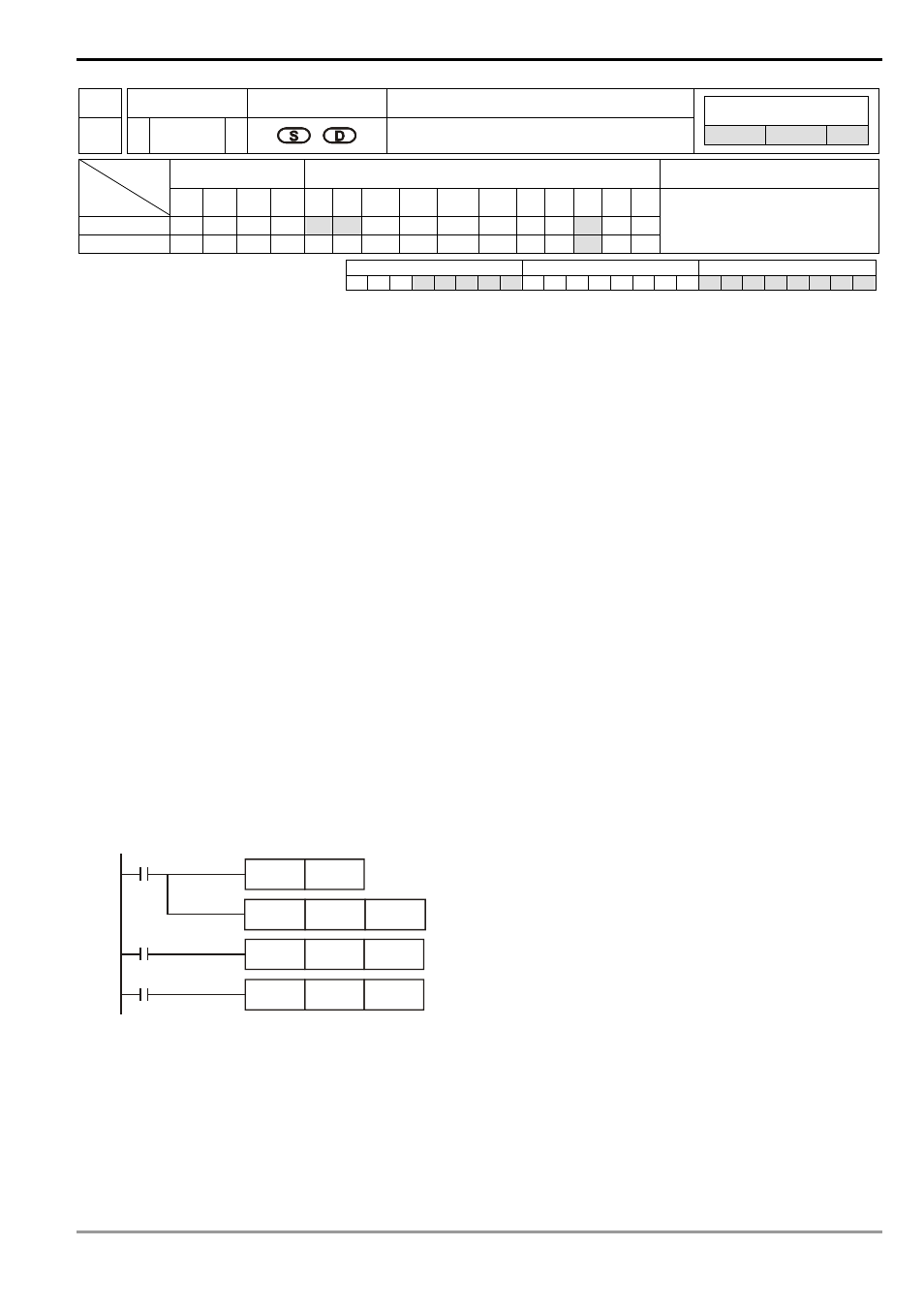
Program Example:
1. When M0 = On, convert (D1, D0) into binary floating point and store it in register (D11, D10).
2. When M1= On, use (D11, D10) as the exponent for EXP operation and store the binary floating point result in
register (D21, D20).
3. When M2 = On, convert the binary floating point (D21, D20) into decimal floating point (D30 × 10
[D31]
) and store
it in register (D31, D30).
M0
RST
M1081
M1
DEXP
D10
D20
M2
DEBCD
D20
D30
DFLT
D0
D10
Remarks:
For floating point operations, see “5.3 Handling of Numeric Values”.