Delta Electronics Programmable Logic Controller DVP-PLC User Manual
Page 376
7 Application Instructions API 50-99
D V P - P L C A P P L I C AT I O N M A N U A L
7-92
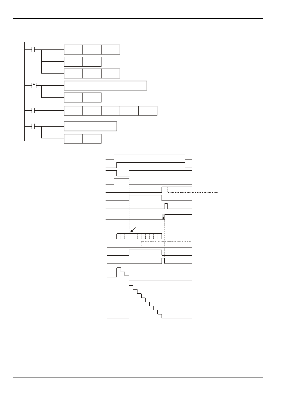
7. Timing diagram of RS-485 communication flag:
MOV
D1120
H86
M1002
SET
M1120
SET
M1122
MOV
D1129
K100
X10
M1123
RST
M1123
RS
D100
K3
D120
K8
Setting communication time out 100ms
Process of received data
Set up communication protocol 9600,7,E,1
Retain communication protocol
Write the data to be transmitted in advance
Set up sending request
Receiving of data is completed.
The flag is reset.
Receiving
completed
Sending request
pulses
8
7
6
5
4
3
2
1
0
3
2
1
0
1 2 3 4 5 6 7 8
1 2 3
SET M1122 X0
MODRD/RDST/MODRW data
receiving and conversion
completed
M1127
MODRD/RDST/MODRW
data converted to hex
M1131
Transmission ready M1121
Sending request M1122
Receiving completed M1123
Waiting for receiving M1124
Communication status cleared M1125
Transmitting and receiving M1128
Receiving time-out M1129
Receiving time-out timer, set by D1129
Remaining words of the sent data D1122
Remaining words of the received data D1123
Auto reset after the data transmission is completed
Converting data
Execution of RS instruction X10
Changing direction
immediately
The user has to do the reset in the program.
Using this in the program will return the
status to the initial transmission ready status.
ASCII data being converted to hex
takes less than 1 scan period.
On when receiving message from the time-out counter
Stop counting when receiving all the data