Delta Electronics Programmable Logic Controller DVP-PLC User Manual
Page 474
9 Application Instructions API 150-199
DVP-PLC Application Manual
9-2
2.
When in ASCII mode, the received data will be stored in the designated registers starting from D0 in ASCII
format and PLC will automatically convert the data into hex value and store them in special registers D1296 ~
D1311. When the conversion into hex value starts, M1131 will be On and turn Off when the conversion is
completed.
3.
If necessary, the user can move the hex values stored in D1296 ~ D1131 to other general registers by using
MOV, DMOV or BMOV instruction. Other instructions of ES/EX/SS do not function on the data in D1296 ~
D1311.
4.
When in RTU mode, the received data will be stored in the designated registers starting from D0 in hex format.
5.
When In ASCII mode or RTU mode, PLC will store the data to be sent in D1256 ~ D1295. If necessary, the
user can move the data to other general registers by using MOV, DMOV or BMOV instruction. Other
instructions of ES/EX/SS do not function on the data in D1256 ~ D1295.
6.
The data sent back from AC motor drive are stored in the registers designated by the user. After the
transmission is completed, PLC will auto-check if the received data are incorrect. M1140 will be On if there is
an error.
7.
If the device address is illegal to a designated communication device, the communication device will respond
with an error message and PLC will store the error code in D1130 and M1141 = On. For example, if 8000H is
illegal to VFD-S, M1141 will be On and D1130 = 2. See user manual of VFD-S for error codes.
8.
After M1140 = On or M1141 = On, PLC will send another correct datum to AC motor drive. If the data sent back
from AC motor drive is correct, M1140 and M1141 will be reset.
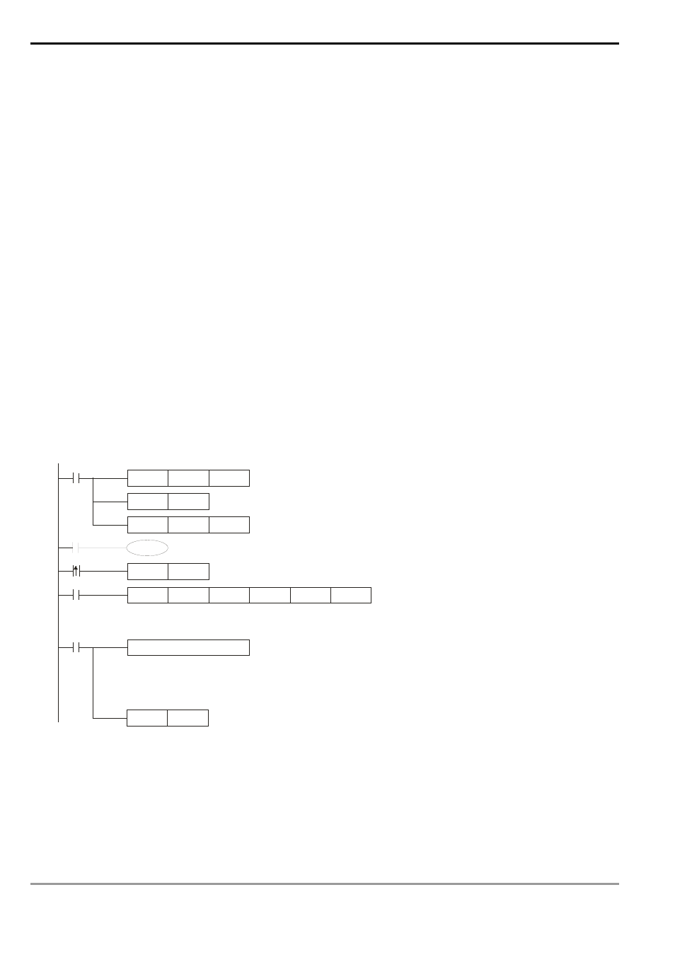
H 87
MOV
M1002
D 1120
SET
M1120
K100
MOV
D 1129
M1127
R ST
M1127
M1143
X10
Set up communication
protocol 9600, 8, E, 1
Retain communication protocol
Communication
time-out 100ms
MOD R W
K3
K1
X0
H 2100
D 0
K6
Address of
communi-
cat ion
device K1
Function
code K3:
read
many data
Data address
H2100
Register
for st oring
the data
Data length
(word)
Process of received data
ASCII mode: The r
eceived data will be stored in the d esignated registers starting
from D0 in ASCII format and PLC will automatically convert the data into hex va lue
and store them in special registers D129 6 ~ D1311.
Sending/receiving of data is completed. The flag is reset.
RTU mode
SET
X0
M1122
Set up sending request
RTU mode: The r
eceived data will be stored in the designated registers starting
from D0 in hex format.
9.
ASCII Mode: When PLC is connected to VFD-S AC motor drive.
PLC
Ö VFD-S, PLC sends: “01 03 2100 0006 D5”
VFD-S
Ö PLC, PLC receives: “01 03 0C 0100 1766 0000 0000 0136 0000 3B”