2 functions of devices in dvp-plc – Delta Electronics Programmable Logic Controller DVP-PLC User Manual
Page 43
2 Functions of Devices in DVP-PLC
DVP-PLC Application Manual
2-15
1-phase 1 input, for
latched
C235 ~ C242, C244, 9 points
1-phase 2 inputs, for
latched
C246, C247, C249, 3 points
(SA/SX) 32-bit counting
up/down high-speed
counter C
2-phase 2 inputs, for
latched
C251 ~ C254, 4 points
Total 16
points
1-phase 1 input, for
latched
C235 ~ C245, 11 points
1-phase 2 inputs, for
latched
C246 ~ C250, 4 points
(SC) 32-bit counting
up/down high-speed
counter C
2-phase 2 inputs, for
latched
C251 ~ C255, 4 points
Can be modified to be
non-latched by setting up
parameters.
Total 19
points
EH/EH2/SV series MPU:
16-bit counting up, for
general purpose
C0 ~ C99, 100 points. Can be modified to be latched by
setting up parameters.
16-bit counting up, for
latched
C100 ~ C199, 100 points. Can be modified to be non-latched
area by setting up parameters.
32-bit counting
up/down, for general
purpose
C200 ~ C219, 20 points. Can be modified to be latched by
setting up parameters.
Counter C
32-bit counting
up/down, for latched
C220 ~ C234, 15 points. Can be modified to be non-latched
by setting up parameters.
Software 1-phase 1
input
C235 ~ C240, 6 points
Hardware 1-phase 1
input
C241 ~ C244, 4 points
Hardware 1-phase 2
inputs
C246 ~ C249, 4 points
32-bit counting up/down
high-speed counter C
Hardware 2-phase 2
inputs
C251 ~ C254, 4 points
Can be modified to be
non-latched by setting up
parameters.
Total
253 points
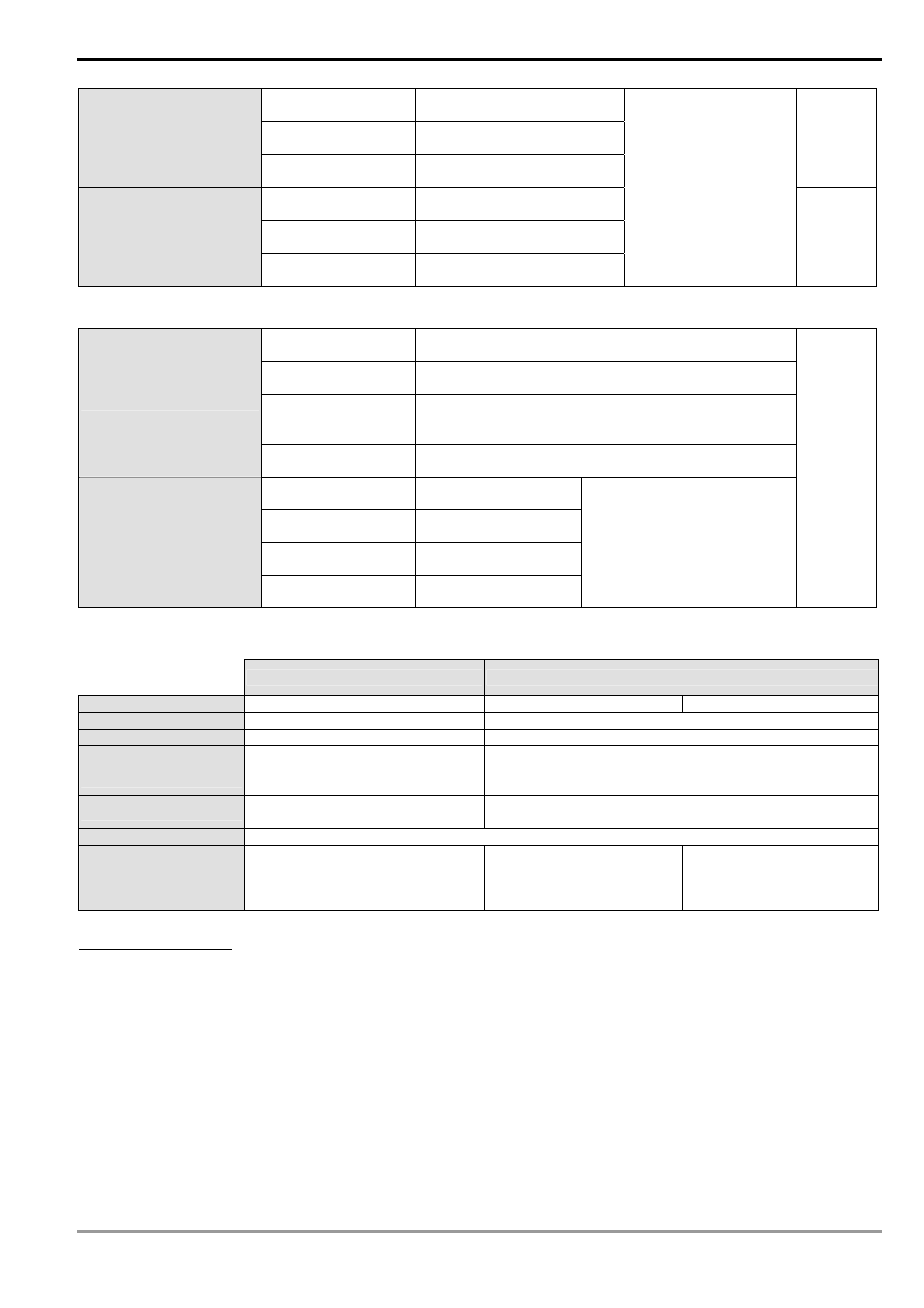
Features of counter:
16 bits counters
32 bits counters
Type
General purpose
General purpose
High speed
Counting direction
Counting up
Counting up, counting down
Set value
0 ~ 32,767
-2,147,483,648 ~ +2,147,483,647
SV designation
Constant K or data register D
Constant K or data register D (designating 2 values)
Present value
Counting will stop when the SV is
reached.
Counter will continue when the SV is reached.
Output contact
On and being retained when the
counting reaches SV.
On and keeps being On when counting up reaches SV.
Reset to Off when counting down reaches SV.
Reset
PV will be return to 0 when RST instruction is executed and the contact will be reset to Off.
Contact action
Acts when the scanning is completed.
Acts when the scanning is
completed.
Acts immediately when the
counting reaches its target,
has nothing to do with the scan
period.
Functions of counters:
When the pulse input signals of the counter go from Off to On and the present value in the counter equals the
set value, the output coil will be On. The set value should be a K value in decimal and the data register D can also be
a set value.
16-bit counters C0 ~ C199:
1. The setup range of 16-bit counter: K0 ~ K32,767. K0 is the same as K1. The output contact will be On
immediately when the first counting starts.
2. PV in the general purpose counter will be cleared when the power of the PLC is switched off. If the counter is a
latched type, the counter will retain the PV and contact status before the power is off and resume the counting