Dvp-plc application manual – Delta Electronics Programmable Logic Controller DVP-PLC User Manual
Page 506
9 Application Instructions API 150-199
DVP-PLC Application Manual
9-34
P1-01: position mode
P1-00: pulse input type as Pulse+DIR.
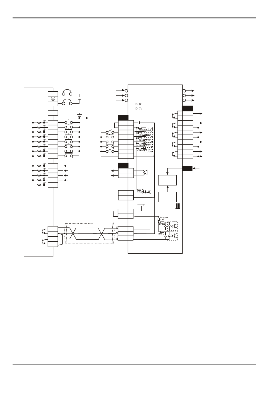
(b)
The forward/reverse limit switch should be connected to SERVO AMP.
(c)
The “clear pulse” signal will clear the current number of pulses left inside the servo.
5.
Wiring of DVP-SC series and Delta ASDA servo drive:
/OZ
50
24V
0V
X0
X1
X2
X3
X4
X5
X20
S/S
JOG(+)
DI 1:
DI 5:
DI 8:
R
S
T
U
V
W
Delta Servo Drive
COM-
DI 2
X21
JOG(-)
DO_COM
X22
X23
X24
X25
X26
SRDY
ZSPD
TPOS
ALARM
CN1
CN2
10
45
Y10
C2
Y0
C0
CN1
26
1
2
3
4
5
6
7
DO1+
DO2+
DO3+
DO4+
DO1-
DO2-
DO3-
DO4-
SRDY
ZSPD
HOME
TPOS
220VAC
24
27
28 DO5+
DO5-
ALARM
OZ
COM-
PLS
41
47
SIGN 37
PU-HI
VDD
17
35
DC24V
24V
CN1
VDD
COM+
DI 1
DI 5
DI 6
DI 7
DI 8
17
11
9
33
32
31
30
COM- 45
DVP12SC11T+DVP16SP11T
24VDC
24VDC
DO_COM
Max. input pulse
frequency: 100kPPS
SC MPU + 16SP
3
-p
h
a
s
e
p
o
w
e
r
ASDA series
S
e
rv
o
m
o
to
r
Servo start
Servo reset
Forward limit
Reverse limit
Emergency stop
Start
Zero return
Start
Error reset
Forward limit
Reverse limit
Differential
signal
Z-phase signal
(zero point signal)
Pulse output
Forward/backward direction
Encoder
Error
counter
Electric
gear
Note:
(a) The parameter setting of Delta ASDA servo drive:
P1-01: position mode
P1-00: pulse input type as Pulse+DIR.
(b) The forward/reverse limit switch should be connected to SERVO AMP.