2 functions of devices in dvp-plc – Delta Electronics Programmable Logic Controller DVP-PLC User Manual
Page 113
2 Functions of Devices in DVP-PLC
DVP-PLC Application Manual
2-85
GF
GP
TF
SF
AP
AP
Frequency
Number of pulses
Number of accel/decel sections = (TF-SF)/GF
Number of output pulses in every section:
GP = AP/Number of accel/decel sections
AP = number of accel/decel pulses
4.
Note: this function is applicable only when “all” the conditions below are met.
a) Start frequency < target frequency.
b) Gap frequency ≤ (target frequency – start frequency)
c) Total number of pulses > (accel/decel number of pulses × 2)
d) For start frequency and target frequency: Min. 25Hz; Max. 10KHz
e) Number of accel/decel pulses > number of accel/decel sections
When M1115 turns from “On” to “Off”, M1119 will be reset and M1116, M1117 and M1118 remain unchanged. When
PLC goes from “STOP” to “RUN”, M1115 ~ M1119 will be reset as “Off”. D1104 will only be cleared as “0” when it
turns from “Off” to “On”.
Either accel/decel pulse output function or PLSY Y0 output can be executed at a time when PLC is operating.
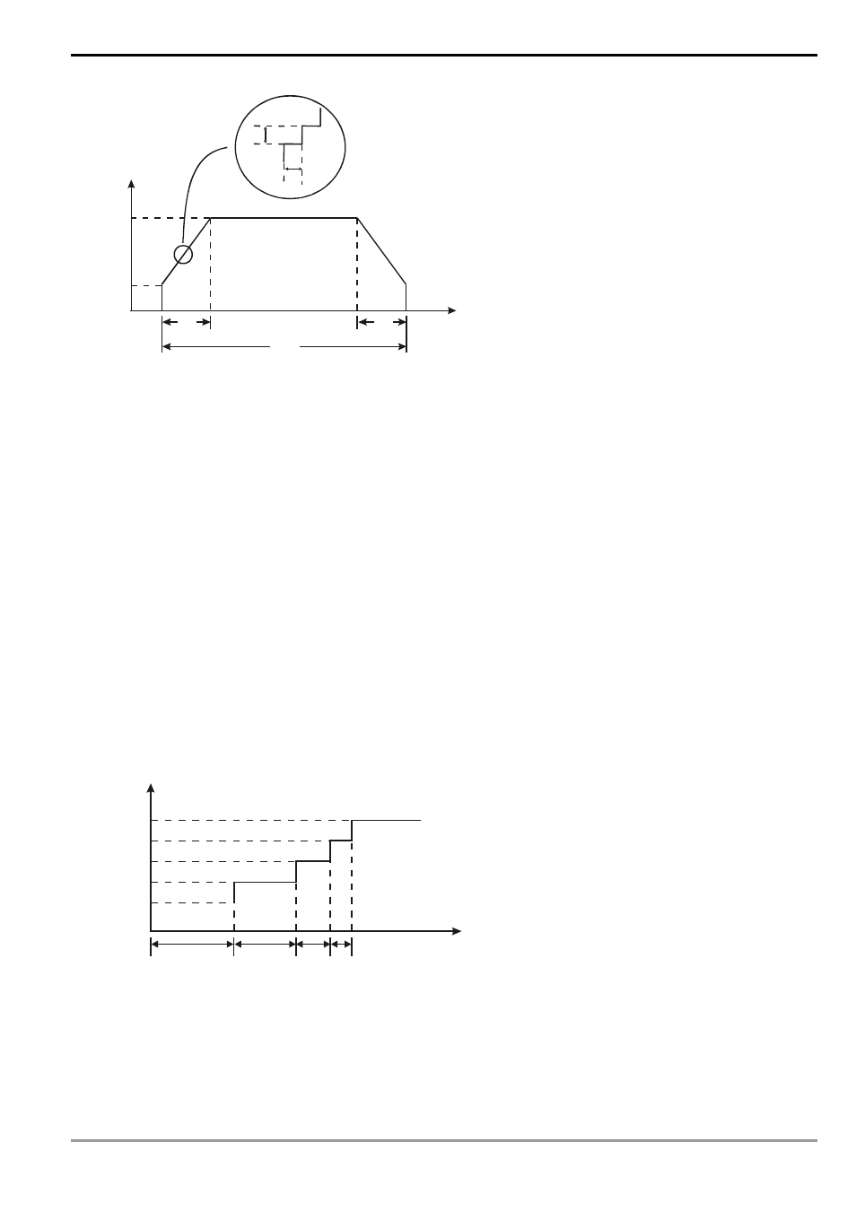
5.
How to calculate the action time of each section
Assume the start frequency is set as 1KHz, gap frequency as 1KHz, target frequency as 5KHz, total number of
pulses as 100 and number of acceleration pulses as 40, the timing diagram of the acceleration sections is as the
figure below.
5,000
4,000
3,000
2,000
1,000
t
t
t
t
1
2
3
4
Frequency (Hz)
Time (sec)
From the conditions above, we can obtain the number of acceleration/deceleration sections is (5K – 1K)/1K = 4
and the number of output pulses in each section is 40/4 = 10. Therefore, in the diagram, t1 = (1/1K) × 10 = 10ms,
t2 = (1/2K) × 10 = 5ms, t3 = (1/3K) × 10 = 3.33ms, t4 = (1/4K) × 10 = 2.5ms.
6.
Program example: Forward/reverse acceleration/deceleration step motor control