Delta Electronics Programmable Logic Controller DVP-PLC User Manual
Page 561
9 Application Instructions API 150-199
DVP-PLC Application Manual
9-89
K0
D214
M1029
DCIMA
Y0
END
K0
D210
DCIMA
Y0
K0
D206
DCIMA
Y0
K0
D202
DCIMA
Y0
= D0 K1
= D0 K2
= D0 K4
M0
K1
D0
D0
M0
M1029
D1336
D1339
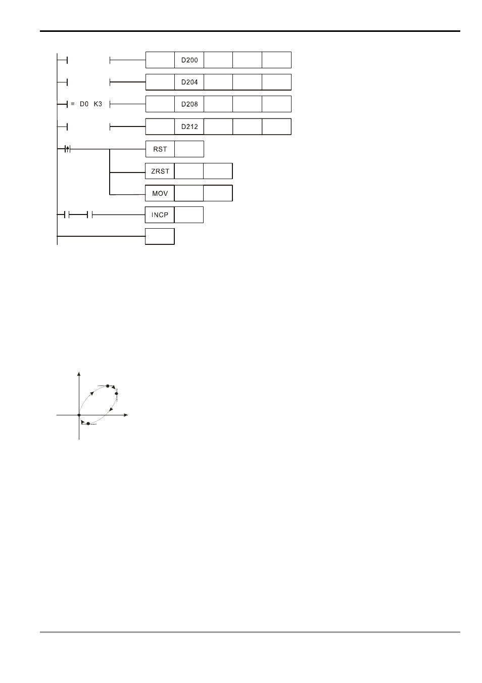
3. Motion explanation:
:
When PLC RUN and M0 = On, PLC will start the drawing of the first segment of the arc. D0 will plus 1 whenever a
segment of arc is completed and the second segment of the arc will start to execute automatically. The same
motion will keep executing until the fourth segment of arc is completed.
Program Example 2:
1. Draw a tilted ellipse as the figure below.
Y
X
(0 ,0)
(2 60 00 ,2 60 00 )
(3 40 00 ,1 80 00 )
(8 00 0,- 80 00 )
2. Steps:
a) Find the max. and min. coordinates on X and Y axes (0,0), (26000,26000), (34000,18000), (8000,-8000) (as the
figure above). Place them respectively in the 32-bit (D200,D202), (D204,D206), (D208,D210) and (D212,D214).
b) Select “draw clockwise arc” and “average resolution” (S = K0).
c) Select DCIMA instruction for drawing arc and write program codes as follows.
d) PLC RUN. Set M0 as On and start the drawing of the ellipse.
- 1x9 Bi-Directional Transceiver Module OPBD-155F2J1R (7 pages)
- Single Mode SFP Transceiver LCP-1250B4MDRx (14 pages)
- LC-1250xxxx Series (10 pages)
- Human Machine Interface DOP-AS Series (329 pages)
- Analog Output Module DVP04DA-S (2 pages)
- DeviceNet Slave Communication Module IFD9502 (2 pages)
- LCP-155B4MSRx (12 pages)
- High-Speed PCI 12-Axis Motion Control Card PCI-DMC-B01 (528 pages)
- Network Device DVP01PU-S (2 pages)
- GBIC-1250D5MR (12 pages)
- SPBD-1250A4Q1RT (10 pages)
- SILM4015 (1 page)
- LCP-8500A4EDR (14 pages)
- 10GBASE-SR SFP+ Optical Transceiver LCP-10G3A4EDR (16 pages)
- LCP-155A4HSRx (11 pages)
- LCP-1250RJ3SR-L (9 pages)
- SILM320L (1 page)
- LCP-1250RJ3SR-S (9 pages)
- SIL530 (1 page)
- Extension Digital I/O Module DOP-EXIO28RAE (1 page)
- DVP Series PLC DVP04TC-H2 (2 pages)
- 1x9 Bi-Directional Transceiver Module OPBD-155F1J1R (7 pages)
- Distribution Box TAP-CN01/02/03 (2 pages)
- LCP-200A4HSR (9 pages)
- Pulse Generation Unit DVP01PU-H2 (2 pages)
- Power Connection Interface VFD-PSD01 (1 page)
- Programmable Logic Controller DVP04DA-H2 (2 pages)
- Single Mode SFP Transceiver LCP-1250B4QDRx (13 pages)
- LCP-155B4JSRx Series (12 pages)
- Series Temperature Controller DTD Series (2 pages)
- Brake Modules BUE Series (2 pages)
- PLC DVP Series DVP-SX (2 pages)
- Digital Keypad / Display ASD-PU-01A (1 page)
- Multimode SFP Transceiver LCP-1250A4FDRx (14 pages)
- HMU1362M (1 page)
- RPA-01 (1 page)
- THMR1395 (1 page)
- SFBD-155F2J1RM (7 pages)
- Program Transfer Module DVP-PCC01 (1 page)
- RTU-DNET (41 pages)
- AC Servo Drive ASDA-AB (37 pages)
- Digital Keypad / Display ASD-PU-01B (1 page)
- HMR1045 (1 page)
- CANopen Communication Module DVPCOPM-SL (2 pages)
- SPBD-1250B4Q1R (10 pages)