Delta Electronics Programmable Logic Controller DVP-PLC User Manual
Page 459
8 Application Instructions API 100-149
DVP-PLC Application Manual
8-57
API Mnemonic
Operands
Function
144
GPWM
General PWM Output
Controllers
ES/EX/SS SA/SX/SC EH/SV
Bit Devices
Word Devices
Program Steps
Type
OP
X Y M S K H
KnX KnY KnM KnS T
C
D
E
F
S
1
*
S
2
*
D
*
*
*
GPWM: 7 steps
PULSE 16-bit 32-bit
ES EX SS SA SX SC EH SV ES EX SS SA SX SC EH SV ES EX SS SA SX SC EH SV
Operands:
S
1
: Width of output pulse S
2
: Pulse output cycle D: Pulse output device
Explanations:
1. S
2
occupies 3 consecutive devices.
2. S
1
≤ S
2
. See the specifications of each model for their range of use.
3. Range
of S
1
: t = 0 ~ 32,767ms.
4. Range
of S
2
: t = 1 ~ 32,767ms.
5. S
2
+1 and S
2
+2 are parameters for the system. Do not occupy them.
6. Pulse output devices D: Y, M, S.
7. When being executed, GPWM instruction designates S
1
and S
2
and that pulses output will be from device D.
8. When
S
1
≤ 0, there will be no pulse output. When S
1
≥ S
2
, the pulse output device will keep being On.
9. S
1
and S
2
can be modified when GPWM instruction is being executed.
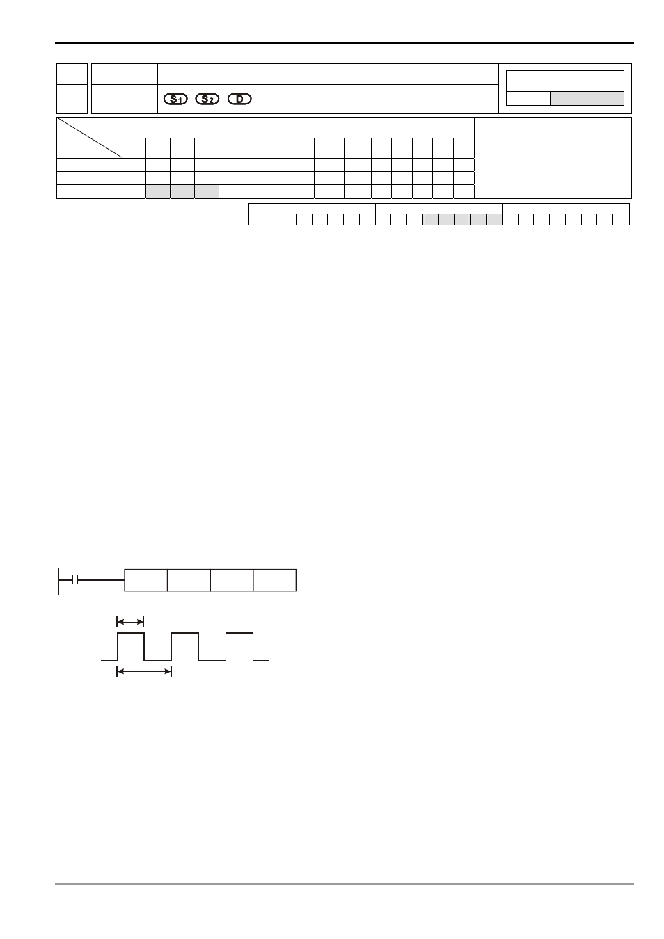
Program Example:
When X0 = On, D0 = K1,000, D2 = K2,000,
and Y10 will output the pulse illustrated below. When X0 = Off, Y10 output
will be Off.
X0
GPWM
D0
D2
Y10
t
T
t=1000ms
T=2000ms
Output Y10
Explanations:
1. This instruction counts by the scan cycle; therefore the maximum offset will be one PLC scan cycle. S
1
, S
2
and
(S
2
- S
1
) should > PLC scan cycle; otherwise, errors will occur during GPWM outputs.
2. Please note that placing this instruction in a subroutine or interruption will cause inaccurate GPWM outputs.