Delta Electronics Programmable Logic Controller DVP-PLC User Manual
Page 336
7 Application Instructions API 50-99
D V P - P L C A P P L I C AT I O N M A N U A L
7-52
API Mnemonic
Operands
Function
65
STMR
Special Timer
Controllers
ES/EX/SS SA/SX/SC EH/SV
Bit Devices
Word Devices
Program Steps
Type
OP
X Y M S K H
KnX
KnY KnM KnS T
C
D
E
F
S
*
m
*
*
D
*
*
*
STMR: 7 steps
PULSE 16-bit 32-bit
ES EX SS SA SX SC EH SV ES EX SS SA SX SC EH SV ES EX SS SA SX SC EH SV
Operands:
S
: No. of timer m: Set value in timer (unit: 100ms) D: No. of start output device
Explanations:
1. Range
of
S
: for SA/SX/SC T0 ~ T191; for EH/EH2/SV T0 ~ T199
2. Range
of
m
: 1 ~ 32,767
3. D will occupy 4 consecutive devices.
4. See the specifications of each model for their range of use.
5. STMR instruction is used for Off-delay, one shot timer and flashing sequence.
6. The No. of timers designated by STMR instructions can be used only once.
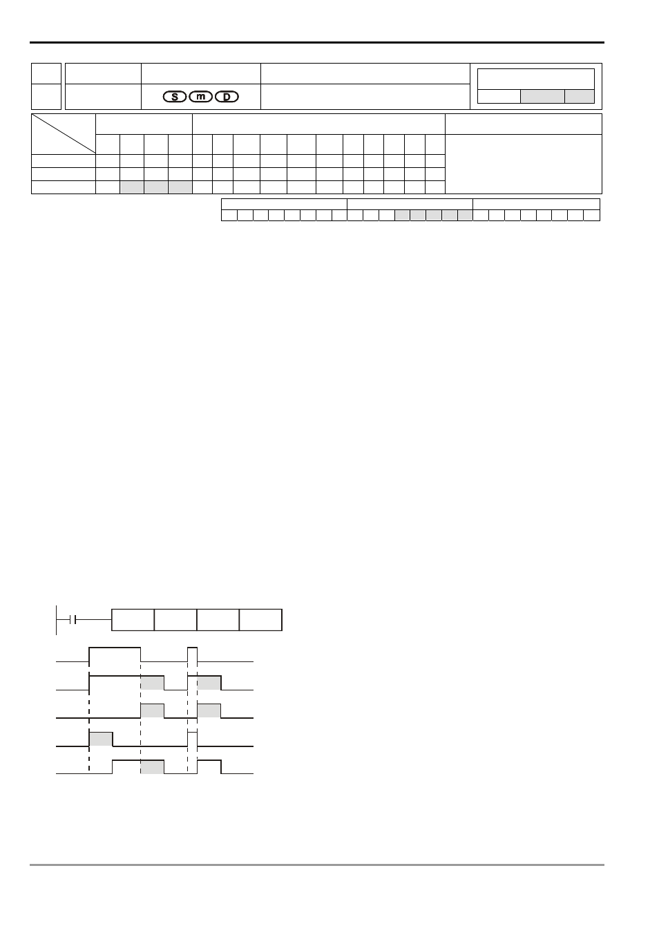
Program Example:
1. When X10 = On, STMR instruction will designate timer T0 and set the set value in T0 as 5 seconds.
2. Y0 is the contact of Off-delay. When X10 goes from Off to On, Y0 will be On. When X10 goes from On to Off, Y0
will be Off after a five seconds of delay.
3. When X10 goes from On to Off, there will be a five seconds of Y1 = On output.
4. When X10 goes from Off to On, there will be a five seconds of Y2 = On output.
5. When X10 goes from Off to On, Y3 will be On after a five seconds of delay. When X10 goes from On to Off, Y3
will be Off after a five seconds of delay.
X10
STMR
T0
K50
Y0
X10
Y0
Y1
Y2
Y3
5 sec
5 sec
5 sec
5 sec
5 sec
5 sec
6. Add a b contact of Y3 after X10, and Y1 and Y2 can operate for flashing sequence output. When X10 goes Off,
Y0, Y1 and Y3 will be Off and the content in T10 will be reset to 0.