Delta Electronics Programmable Logic Controller DVP-PLC User Manual
Page 478
9 Application Instructions API 150-199
DVP-PLC Application Manual
9-6
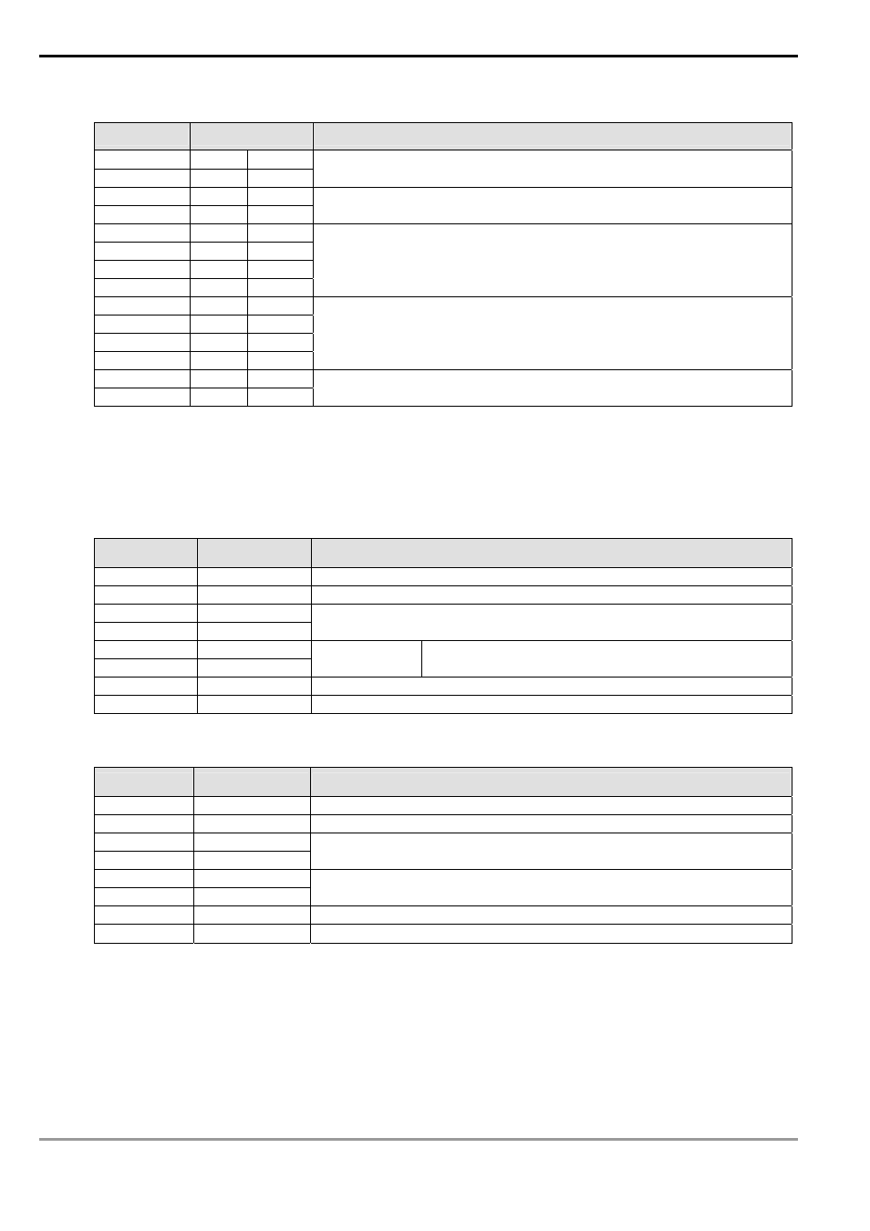
Registers for received data (responding messages)
Register
DATA
Explanation
D1070 Low
‘0’
30 H
ADR 1
D1070 High
‘1’
31 H
ADR 0
D1071 Low
‘0’
30 H
CMD 1
D1071 High
‘6’
36 H
CMD 0
D1072 Low
‘0’
30 H
D1072 High
‘1’
31 H
D1073 Low
‘0’
30 H
D1073 High
‘0’
30 H
Data Address
D1074 Low
‘1’
31 H
D1074 High
‘7’
37 H
D1075 Low
‘7’
37 H
D1075 High
‘0’
30 H
Data content
D1076 Low
‘7’
37 H
LRC CHK 1
D1076 High
‘1’
31 H
LRC CHK 0
9.
RTU Mode: When PLC is connected to VFD-S AC motor drive
PLC
Ö VFD-S, PLC sends: “01 06 2000 0012 02 07”
VFD-S
Ö PLC, PLC receives: “01 06 2000 0012 02 07”
Registers for sent data (sending message)
Register
DATA
Explanation
D1256 Low
01 H
Address
D1257 Low
06 H
Function
D1258 Low
20 H
D1259 Low
00 H
Data Address
D1260 Low
00 H
D1261 Low
12 H
Data content
The content of register D50 (H12)
D1262 Low
02 H
CRC CHK Low
D1263 Low
07 H
CRC CHK High
Registers for received data (responding message)
Register
DATA
Explanation
D1070 Low
01 H
Address
D1071 Low
06 H
Function
D1072 Low
20 H
D1073 Low
00 H
Data Address
D1074 Low
00 H
D1075 Low
12 H
Data content
D1076 Low
02 H
CRC CHK Low
D1077 Low
07 H
CRC CHK High
Program Example 3:
1.
Function code K16(H10): For writing many word data into register.
When PLC is connected to VFD-S AC motor drive: M1143 = Off, in ASCII mode
When PLC is connected to VFD-S AC motor drive: M1143 = On, in RTU mode
2.
When in ASCII mode, the user stores the data to be written in the designated register D50 in hex format. The
data sent back from AC motor drive are stored in D1070 ~ D1076.